Eureka AIR delivers breakthrough ideas for toughest innovation challenges, trusted by R&D personnel around the world.

Linear discrete movable diversion pier for water inlet structure of pump station

A diversion pier, in-line technology, applied in the field of in-line discrete movable diversion piers, can solve the problems of destroying the bad flow state of the vortex, dissipating the energy of the inflow, etc., to improve the flow velocity distribution and pressure distribution conditions, The effect of reducing water flow energy, preventing vibration and noise

Active Publication Date: 2019-05-21
YANGZHOU UNIV
View PDF4 Cites 2 Cited by
  • Summary
  • Abstract
  • Description
  • Claims
  • Application Information

AI Technical Summary

Problems solved by technology

[0004] The purpose of the present invention is to rectify the water flow in the water inlet pool by means of water pressure plates, diversion piers, and columns commonly used in the industry at present. However, a large number of pump stations have a large range of operating water levels, and fixed rectification measures cannot fully adapt to the above water levels. In order to solve the deficiencies such as interval changes, a line-shaped discrete movable diversion pier is proposed for the water inlet structure of the pumping station. The diversion pier can effectively destroy bad flow states such as vortices, and balance the flow on both sides of the diversion pier through the gap. The water volume promotes the redistribution of the water flow velocity, further dissipates the inflow energy, divides the water flowing into the water inlet pool from the channel into two equal parts, and plays a diversion role, providing good water absorption conditions for the water pump inlet pipe, which can improve the stability of the pump station operation performance

Method used


Image

  • Linear discrete movable diversion pier for water inlet structure of pump station
  • Linear discrete movable diversion pier for water inlet structure of pump station
  • Linear discrete movable diversion pier for water inlet structure of pump station

Examples


Embodiment Construction

[0019] The present invention will be further described below in conjunction with accompanying drawing:

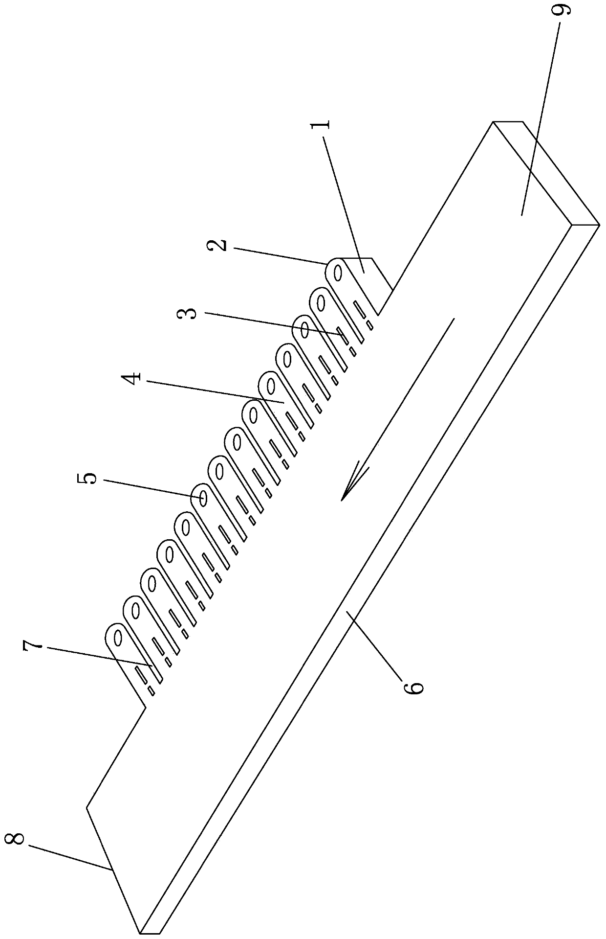
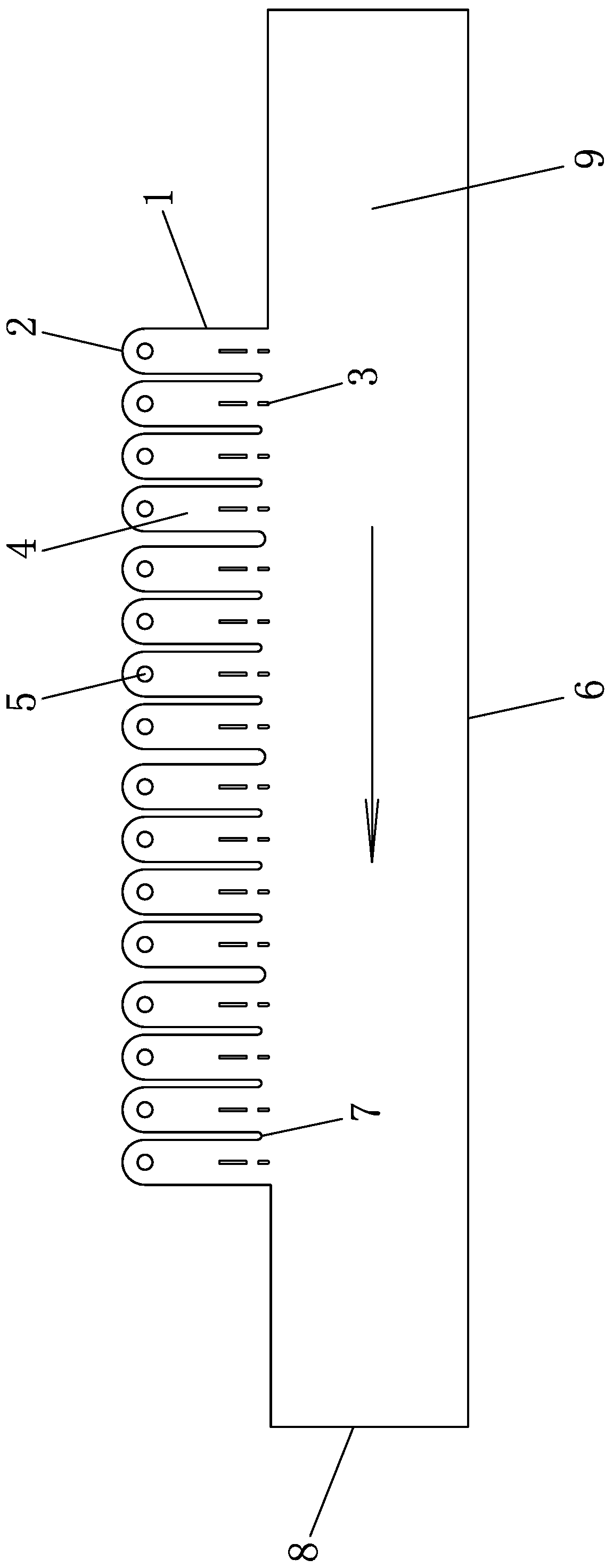
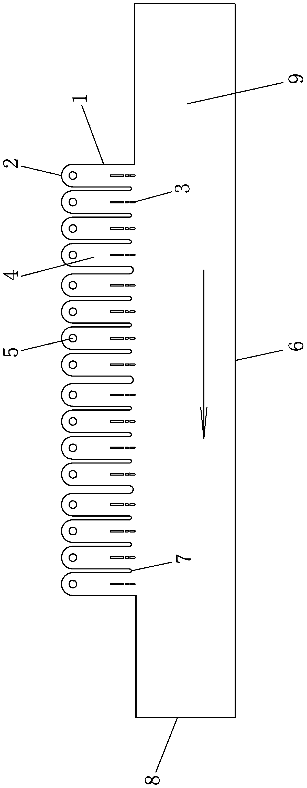
[0020] Such as Figure 1-3 As shown, an inline discrete movable diversion pier for the water intake structure of a pumping station includes a waterway 9 formed by a ship lock 8 and a side slope 6; a number of water inlet pools 4 are arranged on one side of the waterway 9, and the A pier 7 is arranged between the pool 4 and the water inlet pool 4. The water inlet pool 4 is formed by connecting the wing wall 1 and the rear wall 2 of the water inlet pool. The water inlet pipe 5 is provided with several sections of inline diversion piers 3, wherein the first section of inline diversion piers 3 has a circular arc at the head and a rectangular tail, and each section of inline diversion piers 3 is connected to the inlet pool The axes of 4 are parallel, and guide rail is provided at the bottom of water inlet pool 4, and the bottom of every section of inline diversion pier 3 is pro...


PUM


Abstract

The utility model discloses a linear discrete movable diversion pier for a water inlet structure of a pump station, and belongs to the technical field of pump station engineering. Under the conditionthat a navigation function of a ship lock is ensured, the linear discrete movable diversion pier is arranged on central axis of an inlet of a water inlet tank; the number of the discrete diversion piers is determined according to the actual flow state of the water flow; the number of the springs is not more than 3; the water flow transition process is intervened through the linear guide piers; theeffects of shunting and guiding are achieved; the flow deflection effect of water flow is weakened; the possible conditions of vortex and backflow are destroyed; local friction loss is improved; thewater flow energy is reduced; the water flow speed is reduced; the flow velocity distribution and pressure distribution conditions in the water inlet pool are improved; the pressure of the main flow area is kept within a certain range as much as possible; and finally the optimization effect of the water pump water inlet pipe suction condition is achieved. By adjusting gaps of the flow guide piers,the water inlet flow state of the water pump is guaranteed, vibration and noise of the pump station are prevented, and the hydraulic performance and the operation stability of the water pump unit arefurther improved.

Description

technical field [0001] The invention belongs to the technical field of pumping station engineering, and relates to a diversion pier used for the water inlet structure of the pumping station, in particular to improving the unfavorable flow in the water inlet pool of the lock station combined with the pumping station under the condition of ensuring the normal function of the ship lock channel. It is a one-line discrete movable diversion pier. Background technique [0002] The lock station combined pump station is a special pump station, which is composed of ship lock, forebay, side slope, wing wall, inlet pool and pier, etc. It not only undertakes the function of water lifting, but also undertakes other functions such as navigation. When the positive water inlet arrangement cannot be adopted due to factors such as terrain conditions or civil engineering scale, the central axis of the pump station and the central axis of the ship lock often need to be arranged at a certain angl...

Claims


Application Information

Patent Timeline
Patent Type & Authority Applications(China)
IPC IPC(8): E02B3/02E02C1/06
CPCY02A10/30
Inventor 罗灿刘超成立赵开南杨帆夏臣智陈锋许健刘浩
Owner YANGZHOU UNIV
Why Eureka
Eureka Blog
Learn More