Force-transferring intermediate structure

An intermediate structure and intermediate rod technology, applied in the direction of fluid pressure actuating device, etc., can solve the problems of reduced accuracy of measurement results, damaged support structure, and inability to meet the requirements, and achieve the effect of simple structure, ensuring stability and improving work efficiency.

Inactive Publication Date: 2019-05-21
DANYANG CITY XINGUANG ELECTRON
View PDF0 Cites 0 Cited by
  • Summary
  • Abstract
  • Description
  • Claims
  • Application Information

AI Technical Summary

Problems solved by technology

[0002] The force transmission intermediate device, the driving force of the hydraulic cylinder should be applied to one end of the tugboat shaft to balance the axial force on the tugboat, so that it can reach a state of force balance. If the driving force of the hydraulic cylinder cannot act on the tugboat shaft On the axis, then when the thrust is applied to the tugboat shaft, a moment will be given to the tugboat shaft, which will not only reduce the accuracy

Method used


Image

  • Force-transferring intermediate structure

Examples


Embodiment Construction

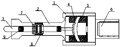
[0015] Such as figure 1 A force transmission intermediate structure shown includes a housing 1, an intermediate rod 3, a push rod 2 and a piston rod 6, one end of the housing 1 is provided with a push rod 2, and the push rod 2 is provided with an intermediate rod 3, and the intermediate rod 3 One end of the middle rod extends into the housing 1 to connect with the thrust bearing 4, and the other end of the middle rod 3 protrudes out of the push rod 2, and the thrust bearing 4 is fitted in the housing 1 through the bearing seat 5, and the housing 1 The other end is provided with a piston rod 6 , and the middle rod 3 is provided with a stroke limiting block 7 .

[0016] In this embodiment, a through hole matching the middle rod 3 is opened in the middle of the travel limit block 7, and is sleeved on the middle rod 3 through the through hole to limit the stroke of the mechanism.

[0017] In this embodiment, the outer end surface of the stroke limiting block 7 is provided with a ...


PUM


Abstract

The invention discloses a force-transferring intermediate structure. The force-transferring intermediate structure comprises a shell, an intermediate rod, a push rod and a piston rod. The push rod isarranged at one end of the shell. The intermediate rod is arranged in the push rod. One end of the intermediate rod stretches into the shell to be connected with a thrust bearing, and the other end ofthe intermediate rod stretches out of the push rod and is convex. The thrust bearing is arranged in the shell in a sleeved mode through a bearing seat. The piston rod is arranged at the other end ofthe shell. A stroke limiting block is arranged on the intermediate rod. The force-transferring intermediate structure is simple; the stroke limiting block is arranged on the intermediate rod in a sleeving mode and has a good limiting effect on the stroke of the mechanism, so that the mechanism is unlikely to get stuck in the force transferring process, the transferring stability of the whole mechanism is ensured, the working efficiency is greatly improved, the service life is remarkably improved, and the cost is low.

Description

technical field [0001] The invention relates to the technical field of precision machining machinery, in particular to a force transmission intermediate structure. Background technique [0002] The force transmission intermediate device, the driving force of the hydraulic cylinder should be applied to one end of the tugboat shaft to balance the axial force on the tugboat, so that it can reach a state of force balance. If the driving force of the hydraulic cylinder cannot act on the tugboat shaft On the axis, then when the thrust is applied to the tugboat shaft, a moment will be given to the tugboat shaft, which will not only reduce the accuracy of the measurement results, but may also damage the supporting structure when the thrust is large, so the force transmission intermediate device The function is to guide the push rod so that the thrust of the hydraulic cylinder is applied to the shaft end of the tugboat shaft. However, the traditional force transmission intermediate d...

Claims


Application Information

Patent Timeline
IPC IPC(8): F15B15/14F15B15/20
Inventor 封毅
Owner DANYANG CITY XINGUANG ELECTRON
Why Eureka
Try Eureka