
Intelligent constant-filling hydraulic coupling

A hydraulic coupling, intelligent technology, applied in the direction of instruments, measuring force, fluid transmission devices, etc., can solve the problems of difficult quality assurance, reduction of overload capacity of working machines, removal of hydraulic coupling, etc.

Pending Publication Date: 2019-05-21
HUNAN ZHONGTE HYDRAULIC ROTARY TRANSMISSION MACHINE
View PDF12 Cites 5 Cited by
  • Summary
  • Abstract
  • Description
  • Claims
  • Application Information

AI Technical Summary

Problems solved by technology

As the ultimate overload protection of the fixed-fill hydraulic coupling for the whole machine, whether it is spraying liquid through the safety plug or using the anti-blowout safety plug, there are deficiencies: when the fusible safety plug is used for liquid spraying protection, the sprayed working medium The site environment is polluted to some extent, and the high-temperature liquid may cause harm to the surrounding personnel. To restore the operation of the hydraulic coupling, it is necessary to refill the fluid and replace the safety plug, which is troublesome to operate; however, the use of the anti-blowout safety plug can avoid the ejection of the working medium , but because of its low operating temperature setting (the anti-blowout safety plug must be used in conjunction with the fusible safety plug, the action temperature of the anti-blowout safety plug is much lower than the melt blown temperature of the fusible safety plug), which will make the overload capacity of the working machine It is greatly reduced, and the anti-blowout safety plug must also be replaced to restore the operation of the hydraulic coupling
However, there are firstly that the machining accuracy of the thread of the screw sleeve is high, the processing is difficult, and the quality is difficult to guarantee. The thread fit precision of the screw sleeve and the dismounting screw is not high, the frictional resistance is large, and the strength of the thread is not enough, which may easily lead to thread damage; the second is disassembly. Inconvenient, in order to fix the motor shaft or reducer shaft, you need to remove the motor fan guard first, and then remove the fan blades
[0005] When there is no screw sleeve or the screw sleeve is damaged, the old hydraulic coupling cannot be removed, it can only be damaged and disassembled, and cannot be inspected and repaired, which not only causes certain economic losses, but more seriously delays normal production

Method used


Image

  • Intelligent constant-filling hydraulic coupling
  • Intelligent constant-filling hydraulic coupling
  • Intelligent constant-filling hydraulic coupling

Examples


Embodiment 1

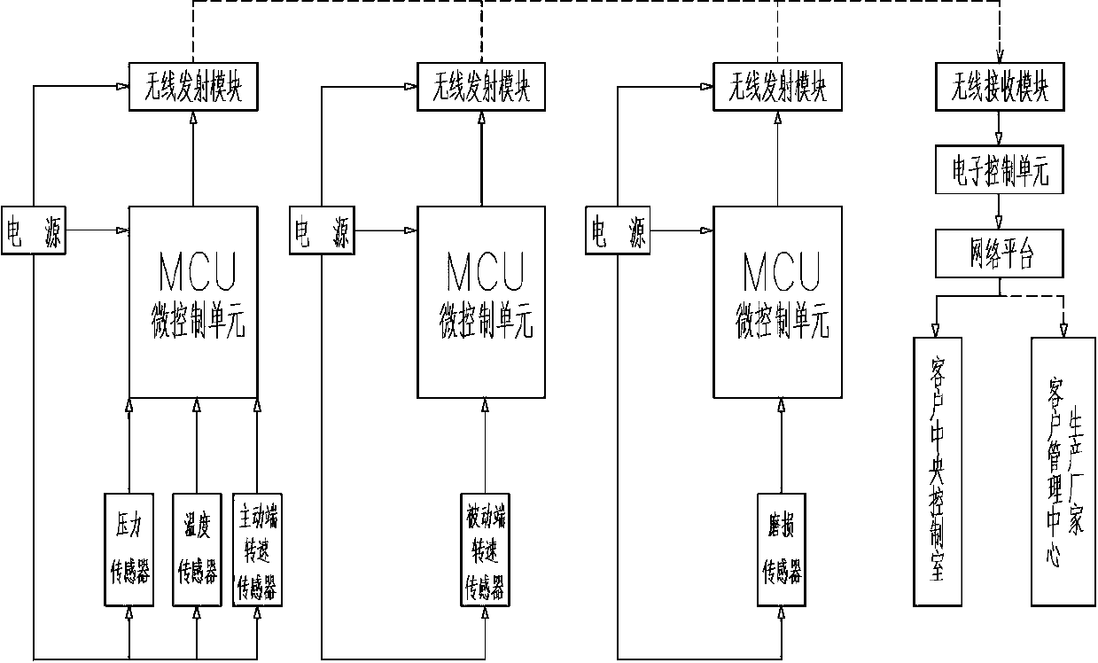
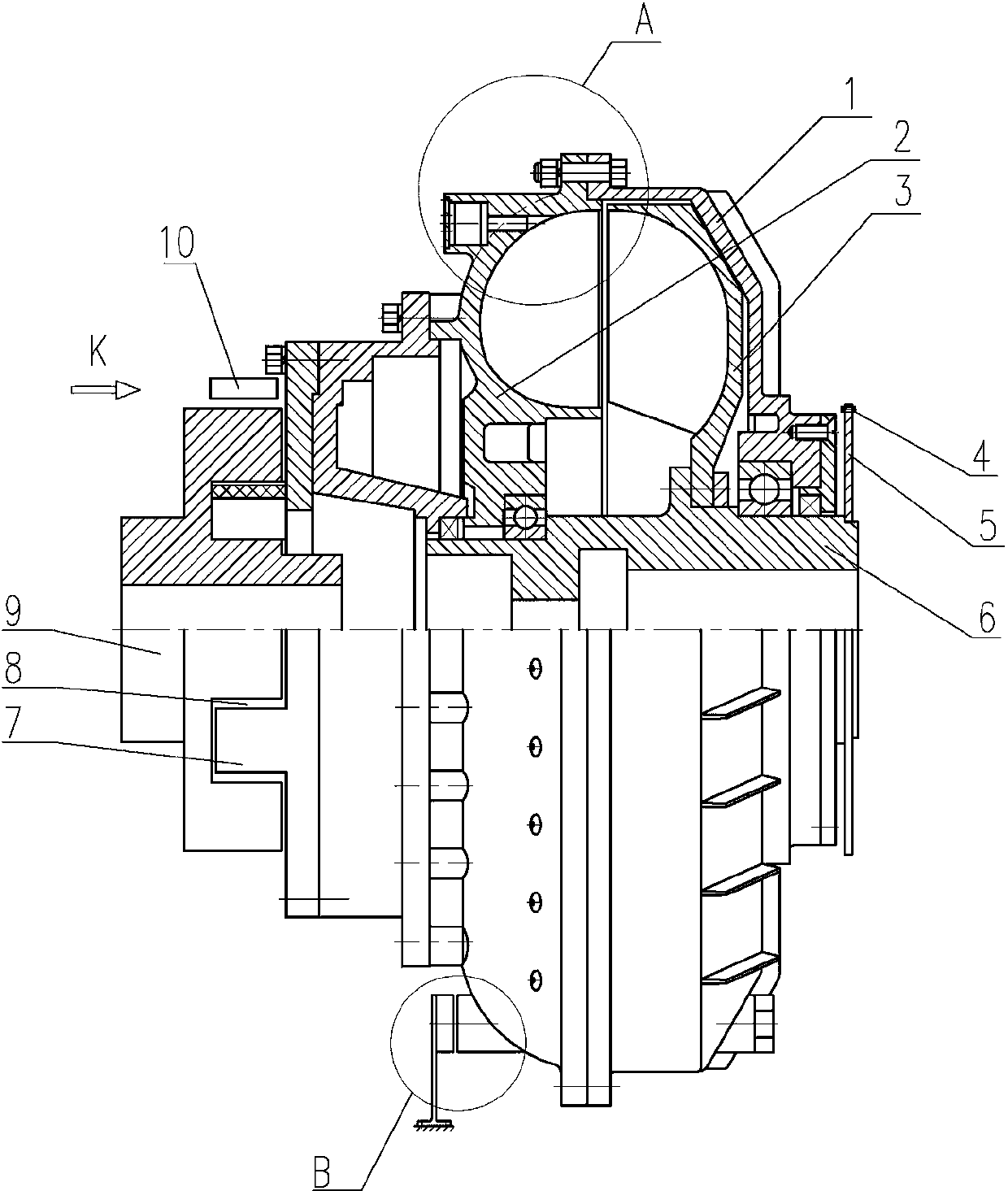
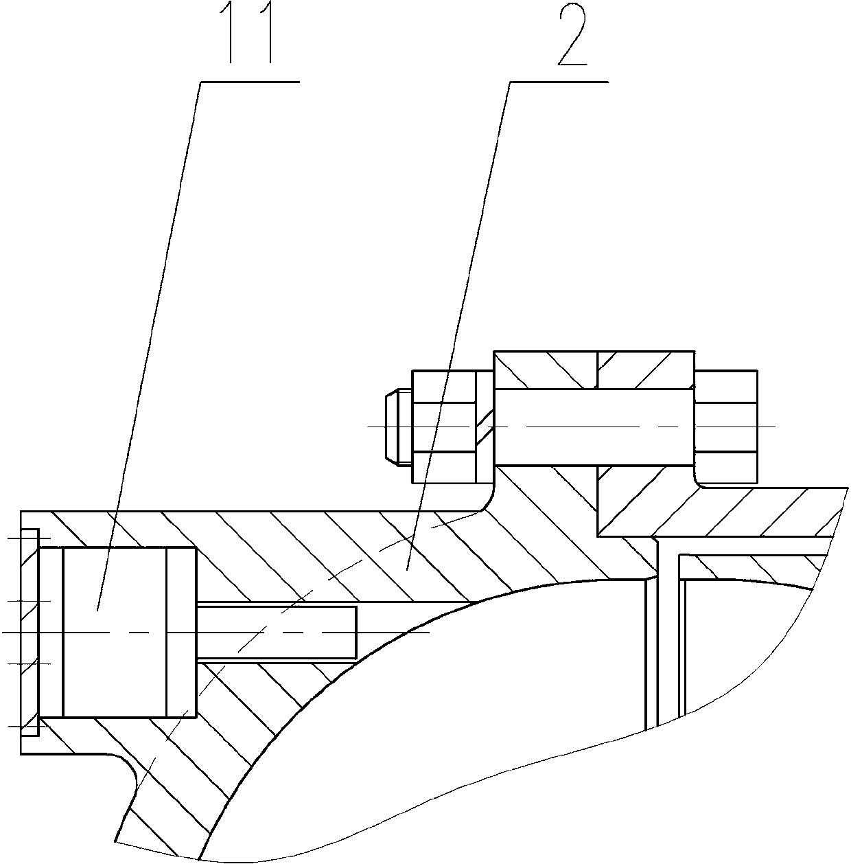
[0031] Depend on figure 1 , figure 2 , image 3 , Figure 5 , Figure 7 It can be seen that an intelligent fixed-fill hydraulic coupling includes a casing 1, a pump wheel 2, a turbine 3 installed on the main shaft 6, and an elastic coupling connected to the pump wheel 2. On the casing 1 or the pump wheel 2 A pressure sensor for detecting the pressure in the working chamber of the hydraulic coupling, a temperature sensor for detecting the temperature of the working medium, and an active-end speed sensor for detecting the speed of the pump wheel are provided, and a passive-side speed sensor for detecting the speed of the turbine 3 is installed on the main shaft 6; The sensor signals at the active end of the force coupling and the sensor signals at the passive end of the hydraulic coupling are collected and sent to their respective MCU micro-control units for processing, and then transmitted through the wireless transmitting module, and then transmitted to the electronic cont...

Embodiment 2

[0056] Depend on Figure 4 , Figure 6 It can be seen that the wear sensor 10 of this embodiment and the corresponding power supply, MCU micro control unit, and wireless transmission module are installed on the active joint 9, and the driven claw 17 of the driven joint 7 is provided with an induction head 16 corresponding to the wear sensor 10 . When the elastic block 8 is worn out, the driven joint 7 deflects, so that the induction head 16 on the driven claw 17 corresponds to the wear sensor 10, thereby sending out a wear signal of the elastic block, which is transmitted through the corresponding MCU micro control unit and the wireless transmission module. After being received by the wireless receiving module, it is sent to the electronic control unit, and the electronic control unit gives an alarm to remind the customer to replace the elastic block 8 .

[0057] The power supply of this embodiment adopts a power generation mechanism installed on the hydraulic coupling, and ...


PUM


Abstract

The invention discloses an intelligent constant-filling hydraulic coupling. The working conditions of the intelligent constant-filling hydraulic coupling can be detected online in real time, and the intelligent constant-filling hydraulic coupling is convenient to disassemble or assemble. The intelligent constant-filling hydraulic coupling is characterized in that a pressure sensor, a temperature sensor and a driving end rotating speed sensor are arranged on a shell or a pump wheel; a driven end rotating speed sensor is arranged on a main shaft; sensor signals are collected and sent into corresponding micro-control units (MCUs) to be processed, are then transmitted through a wireless emission module, and are received by a wireless receiving module and then transmitted to an electronic control unit, so that real-time detection of the working condition of the hydraulic coupling is realized; and meanwhile, an expansion sleeve is arranged in a main shaft assembly end inner hole, a shaft hole is formed in the expansion sleeve, the outer surface of the expansion sleeve is connected with the inner surface of the main shaft assembly end inner hole through a sectional wedge-shaped conical surface, an axial through groove is formed in the expansion sleeve, one end of the expansion sleeve is connected with a locking nut, and the locking nut is connected with the main shaft assembly end inner hole through threads. By means of the intelligent constant-filling hydraulic coupling, the working condition of the hydraulic coupling can be detected online in real time, so that the intelligent management of equipment can be realized by a customer. Moreover, a connecting device enables the hydraulic coupling to be disassembled or assembled conveniently.

Description

technical field [0001] The present invention relates to a hydraulic coupling, in particular to a constant filling type hydraulic coupling, in particular to a constant filling type hydraulic coupling which can detect the working condition of the constant filling type on-line and in real time and is convenient for the disassembly or installation of the hydraulic coupling Intelligent fixed-fill hydraulic coupling. Background technique [0002] Fixed filling type (torque-limiting type, common type) hydraulic couplings are widely used because of their characteristics that other transmission methods do not have. Since the fixed-fill hydraulic coupling is a closed transmission element, it is impossible to adjust its liquid filling volume during its operation. When the fixed-fill hydraulic coupling encounters severe overload of the working machine, it will reduce the output speed until it stalls (output zero transmission speed) to realize torque limit protection for the entire tran...

Claims


Application Information

Patent Timeline
Patent Type & Authority Applications(China)
IPC IPC(8): F16H41/04F16H41/24G01P3/00G01L1/00G01R19/00
Inventor 孙军红吴立平臧剑光张帆李孟秋
Owner HUNAN ZHONGTE HYDRAULIC ROTARY TRANSMISSION MACHINE
Learn More