A method for calculating the time-varying meshing stiffness of an internal meshing gear pair of a straight-tooth cylindrical gear

A technology of spur gears and time-varying meshing stiffness, which is applied in calculation, instrumentation, electrical digital data processing, etc., and can solve problems such as complex modeling process, time-consuming, and insufficient accuracy

Active Publication Date: 2019-05-21
SOUTH CHINA UNIV OF TECH
View PDF4 Cites 9 Cited by
  • Summary
  • Abstract
  • Description
  • Claims
  • Application Information

AI Technical Summary

Problems solved by technology

The finite element method needs to model each meshing gear and set the contact relationship. The modeling process is complicated and the calculation efficiency is not high. At the same time, the accuracy of the calculation results is also affected by the mesh quality.
The Ishikawa formula method is equivalent to a gear as a cantilever beam composed of a trapezoid and a rectangle. The calculation is simple but the accuracy is not enough
The analytic method uses material mechanics to obtain the analytic equation of the gear involute without any modification by equating the gear tooth to a cantilever beam. The calculation accuracy is relatively high, but most of the existing methods are based on the single-point calculation of the mesh stiffness, and the time-varying mesh stiffness The calculation also needs to know the information of each point in advance (the distance from the meshing point to the cantilever beam or the meshing angle). This information needs to be obtained separately, and it is essentially repetitive and time-consuming for different gear teeth, which is not simple and convenient enough.

Method used


Image

  • A method for calculating the time-varying meshing stiffness of an internal meshing gear pair of a straight-tooth cylindrical gear
  • A method for calculating the time-varying meshing stiffness of an internal meshing gear pair of a straight-tooth cylindrical gear
  • A method for calculating the time-varying meshing stiffness of an internal meshing gear pair of a straight-tooth cylindrical gear

Examples


Embodiment Construction

[0090] In order to explain the present invention more clearly, the following embodiments are described in detail in conjunction with the accompanying drawings.

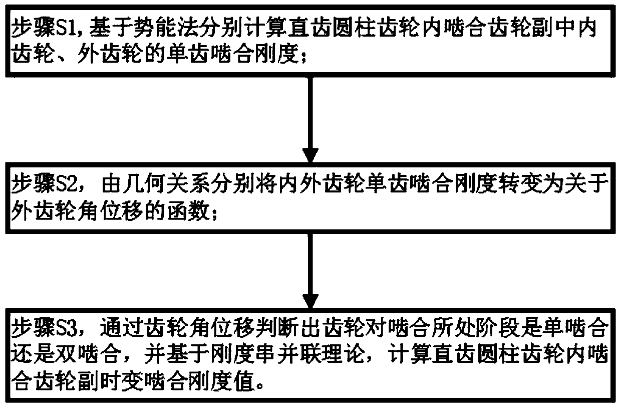
[0091] figure 1 It is a flowchart of a method for calculating the time-varying meshing stiffness of a spur gear internal meshing gear pair disclosed in the present invention, combining figure 1 , the steps of the specific embodiment of the present invention are:

[0092] Step S1, calculating the meshing stiffness of a single tooth of the internal and external gears in the spur gear internal meshing gear pair, specifically including:

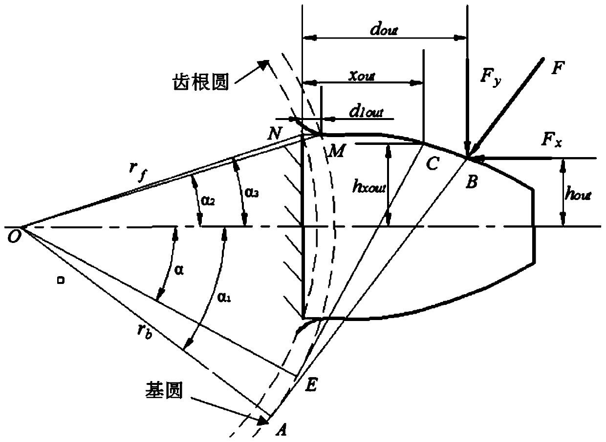
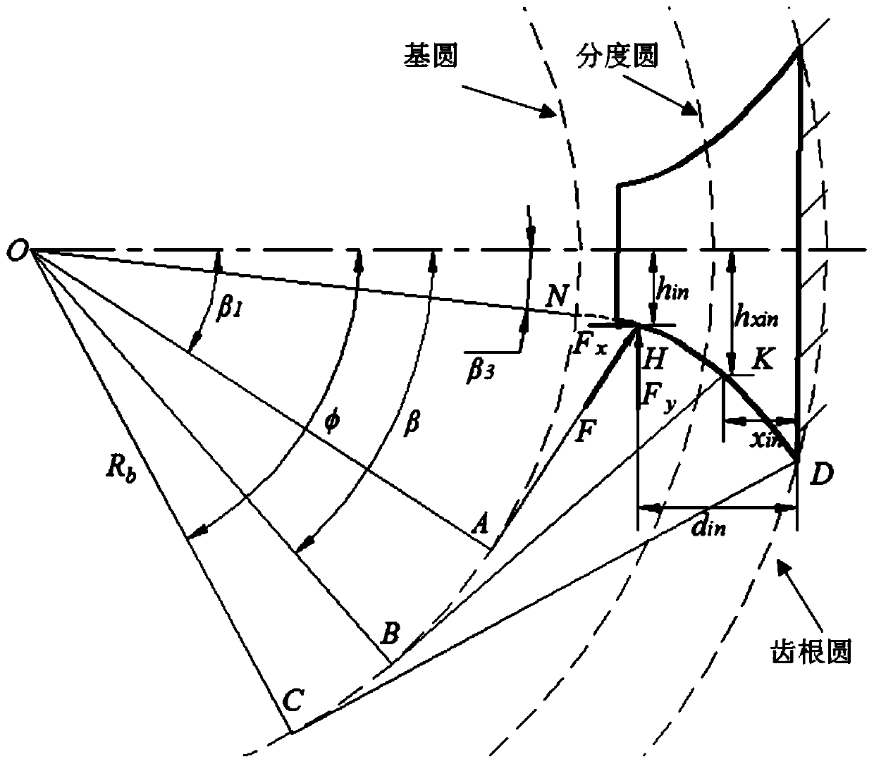
[0093] In step S11, the teeth of the internal and external gears are equivalent to a cantilever beam, and the contour shape of the cantilever beam is judged based on the relationship between the addendum circle and base circle diameter of the internal gear, and the dedendum circle and base circle diameter of the external gear;

[0094] When the gear teeth mesh, the deformation of the g...


PUM


Abstract

The invention discloses a method for calculating the time-varying meshing stiffness of an internal meshing gear pair of a straight-tooth cylindrical gear. The method comprises the following steps thatS1, single-tooth meshing stiffness of an inner gear and an outer gear in a straight-tooth cylindrical gear inner meshing gear pair is calculated on the basis of a potential energy method; S2, the single-tooth meshing stiffness of the inner gear and the outer gear is converted into a function about the angular displacement of the outer gear according to the geometrical relationship; And S3, whether the stage of gear pair meshing is single meshing or double meshing is judged through gear angular displacement, and the time-varying meshing stiffness value of the inner meshing gear pair of the straight-tooth cylindrical gear is calculated on the basis of the stiffness series-parallel theory. On one hand, the blank of a time-varying stiffness calculation method of the gear under internal meshing at the present stage can be made up, and on the other hand, solving can be simplified and the calculation efficiency can be improved by combining gear geometric information on the basis of giving play to the high-precision advantage of an analytical method.

Description

technical field [0001] The invention belongs to the technical field of mechanical dynamics, and in particular relates to a calculation method for the time-varying meshing stiffness of a spur gear internal meshing gear pair, which can be used for dynamic performance analysis of a gear transmission system including the internal meshing gear pair. Background technique [0002] Gear transmission is one of the most widely used transmission forms in the field of mechanical transmission. The specific motion pairs include external meshing gear pairs, internal meshing gear pairs and rack and pinion pairs. Affected by the number of contact tooth pairs and the contact position of the gear teeth, the meshing stiffness of the gear is a periodic function that changes with time, and then becomes one of the main excitation sources that cause the vibration of the gear transmission system. Therefore, an accurate and effective calculation method for time-varying mesh stiffness of gears is esse...

Claims


Application Information

Patent Timeline
Patent Type & Authority Applications(China)
IPC IPC(8): G06F17/50
Inventor 孙亚林何国林丁康
Owner SOUTH CHINA UNIV OF TECH
Why Eureka
Try Eureka