A system for testing ONU radiation emissions having a plurality of Ethernet ports

A technology of radiation emission and Ethernet, which is applied in the field of optoelectronic communication, can solve the problems of incoordination, insufficient testing, and high requirements for darkroom input and output filtering, and achieve the effect of convenient operation and simple structure

Pending Publication Date: 2019-05-21
TAICANG T&W ELECTRONICS CO LTD
View PDF0 Cites 0 Cited by
  • Summary
  • Abstract
  • Description
  • Claims
  • Application Information

AI Technical Summary

Problems solved by technology

In the ONU, there is a device with multiple (more than 4, sometimes up to 24) Ethernet ports. During the radiated emission RE test, it is difficult to lead out the half-wave anechoic chamber from the Ethernet multi-port, because the input and output filtering requirements of the anechoic chamber are high. , the usual EMC semi-anechoic chamber does not have so many Ethernet ports, and it is impossible to lead the Ethernet ports out of the darkroom. If the streaming equipment is moved into the darkroom, it will cause all kinds of troubles, especially the radiation of the streaming equipment itself may not be able to To coordinate with the standard of the equipment under test, connect the Ethernet multi-port on the ONU to the auxiliary test switch, and then lead out an Ethernet port to the streaming device outside the dark room. There is also the problem of inconsistency between the radiation emission of the switch and the ONU. At the same time, the test is not rigorous enough

Method used


Image

  • A system for testing ONU radiation emissions having a plurality of Ethernet ports
  • A system for testing ONU radiation emissions having a plurality of Ethernet ports

Examples


Embodiment 1

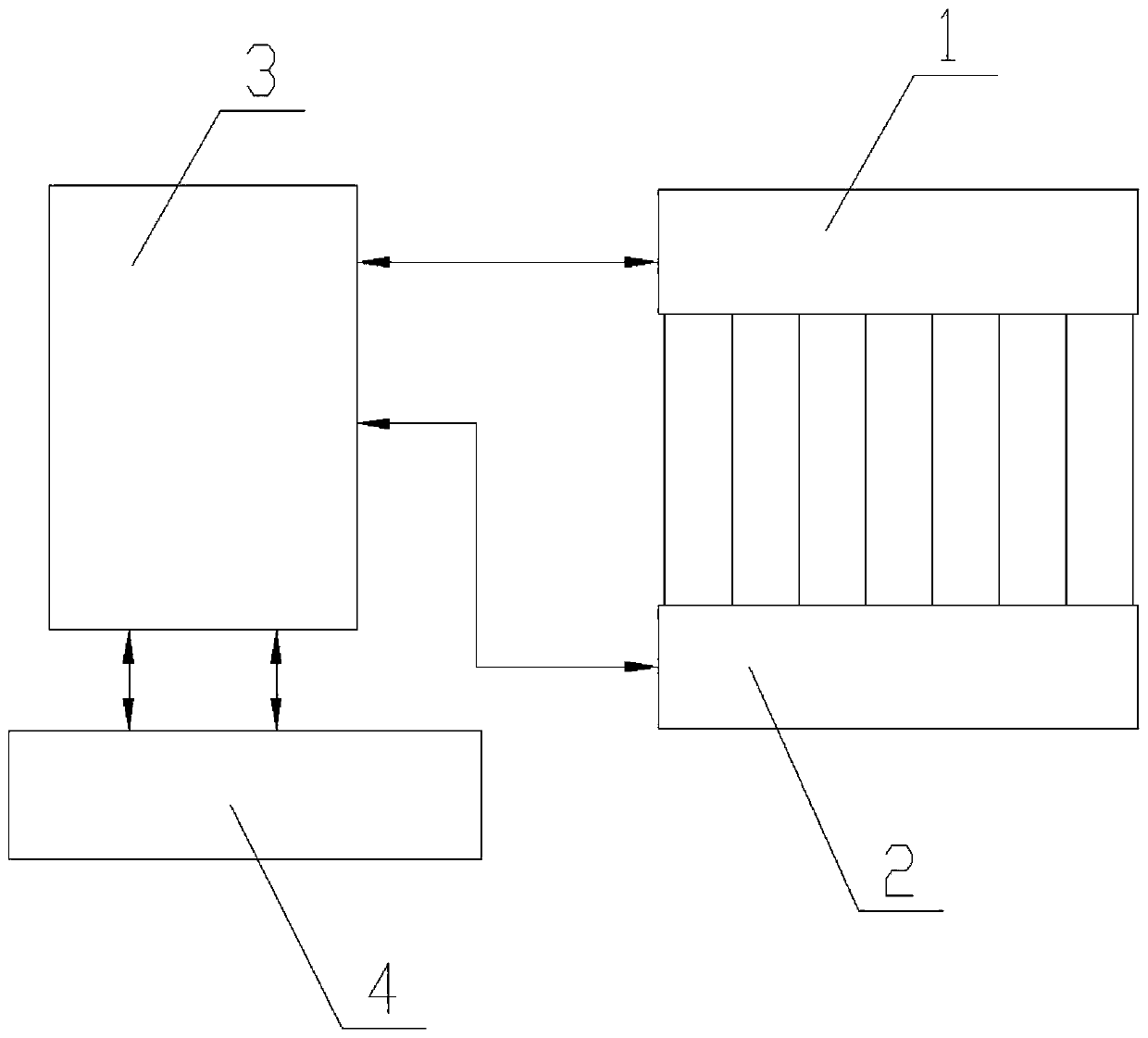
[0015] Embodiment 1: as figure 1 A system for testing the radiated emission of an ONU with multiple Ethernet ports is shown, including the ONU1 under test and the ONU2 under test located in a semi-anechoic chamber, and the OLT3 and flow device 4 located outside the semi-anechoic chamber, The eight Ethernet ports of the ONU1 under test are respectively connected to the eight Ethernet ports of the accompanying ONU2 through network cables, and the optical fibers of the ONU1 under test and the ONU2 under test are led out of the semi-anechoic chamber and connected to the interface board of the OLT3. The uplink optical port of the OLT3 is connected to the streaming device 4 for streaming analysis. In this embodiment, the optical fibers of the ONU1 under test and the ONU2 under test respectively lead out from the dark room to two single-fiber WDM channels of the PON passive optical network interface board connected to the OLT3 (optical line terminal), and the two uplinks of the OLT3 ...

Embodiment 2

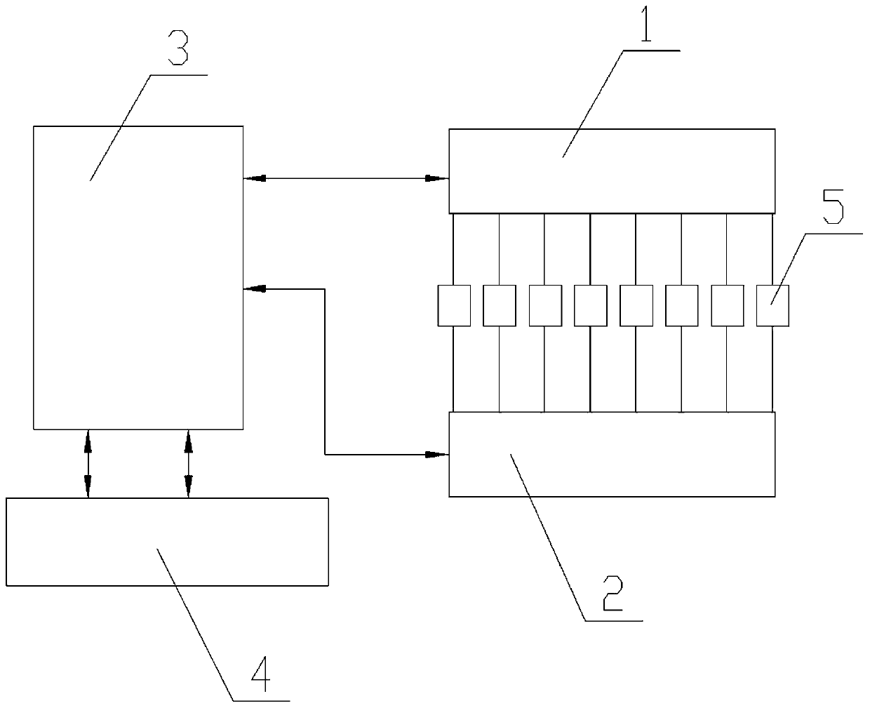
[0016] Embodiment 2: as figure 2 As shown, the difference between it and Embodiment 1 is: it also includes a PD load board 5, and the Ethernet port of the ONU1 under test is connected to the port of the PD load board 5 and then connected to the Ethernet port of the accompanying ONU2 for testing. The PD load board 5 is used to verify whether the PSE power supply function of the ONU is normal, and is applicable to the ONU with the PSE function.


PUM


Abstract

The invention discloses a system for testing ONU radiation emission with a plurality of Ethernet ports. The system comprises a tested ONU and a test accompanying ONU which are located in a semi-anechoic chamber, and an OLT and a flow striking device which are located outside the semi-anechoic chamber. A plurality of Ethernet ports of the tested ONU are respectively connected with an Ethernet portof the accompanying tested ONU through network cables, optical fibers of the tested ONU and the accompanying tested ONU are led out of a semi-anechoic chamber and then are connected to an interface board of the OLT, and an uplink optical port of the OLT is connected to a flow striking device. The device is simple in structure, is suitable for ONU equipment with a plurality of Ethernet ports, is convenient to operate, and can truly and effectively test the radiation emission of the tested ONU.

Description

technical field [0001] The invention belongs to the technical field of optoelectronic communication, in particular to a system for testing radiation emission of an ONU with multiple Ethernet ports. Background technique [0002] As a terminal communication device, the ONU optical network unit is used more and more widely. In the ONU, there is a device with multiple (more than 4, sometimes up to 24) Ethernet ports. During the radiated emission RE test, it is difficult to lead out the half-wave anechoic chamber from the Ethernet multi-port, because the input and output filtering requirements of the anechoic chamber are high. , the usual EMC semi-anechoic chamber does not have so many Ethernet ports, and it is impossible to lead the Ethernet ports out of the darkroom. If the streaming equipment is moved into the darkroom, it will cause all kinds of troubles, especially the radiation of the streaming equipment itself may not be able to To coordinate with the standard of the equi...

Claims


Application Information

Patent Timeline
Patent Type & Authority Applications(China)
IPC IPC(8): H04B10/079
Inventor 蔡云枝王海波王慧董庆
Owner TAICANG T&W ELECTRONICS CO LTD
Why Eureka
Try Eureka