One piece oil control ring for internal combustion engine

A one-piece, internal combustion engine technology applied in the field of oil control rings that can solve problems such as no revealed solutions

Inactive Publication Date: 2019-05-21
MAHLE METAL LEVE +1
View PDF6 Cites 0 Cited by
  • Summary
  • Abstract
  • Description
  • Claims
  • Application Information

AI Technical Summary

Problems solved by technology

However, document BR102012028094-9 does not reveal any solution in the sense of reducing the wear experienced by the single-piece oil ring

Method used


Image

  • One piece oil control ring for internal combustion engine
  • One piece oil control ring for internal combustion engine
  • One piece oil control ring for internal combustion engine

Examples


Embodiment Construction

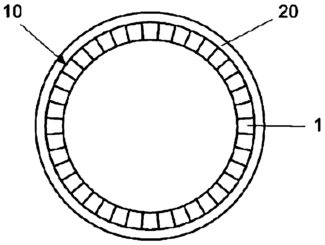
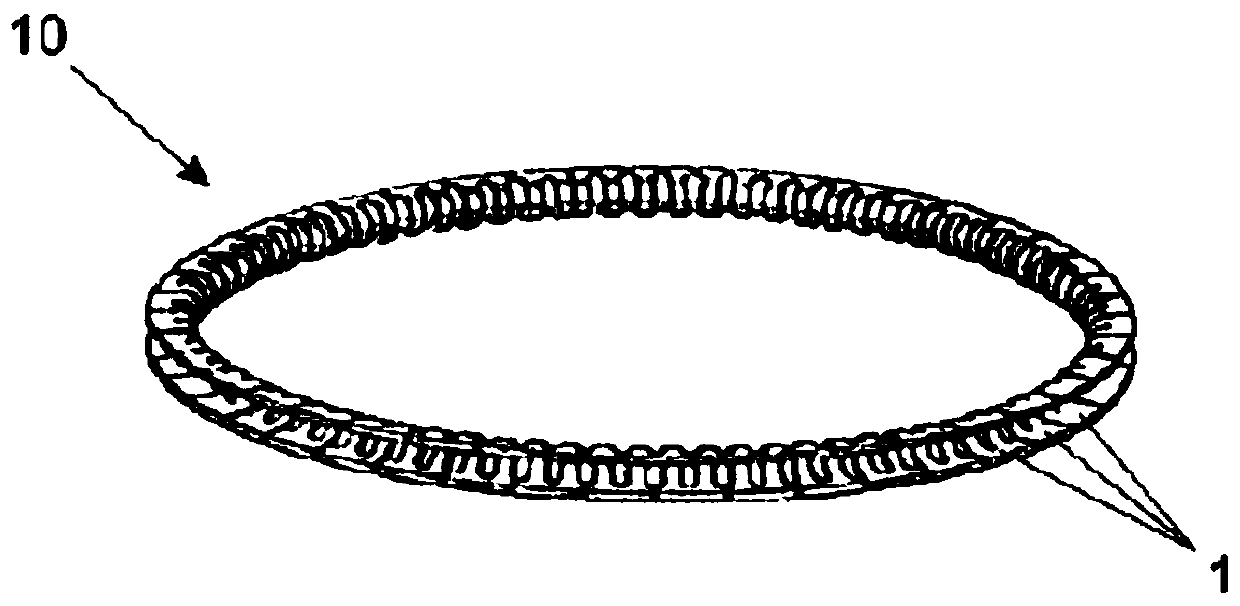
[0029] According to a preferred embodiment, and as in figure 1 with figure 2 As can be seen in , the subject one-piece oil control ring 10 of the present invention comprises a body formed of a plurality of operably associated segments 1, each segment having a degree of freedom of movement relative to the rest, Giving the ring 10 great flexibility, and thus great adaptability or moldability to the form of the cylinder liner 20, ensures that a proper oil film is maintained under a wide variety of engine operating conditions.

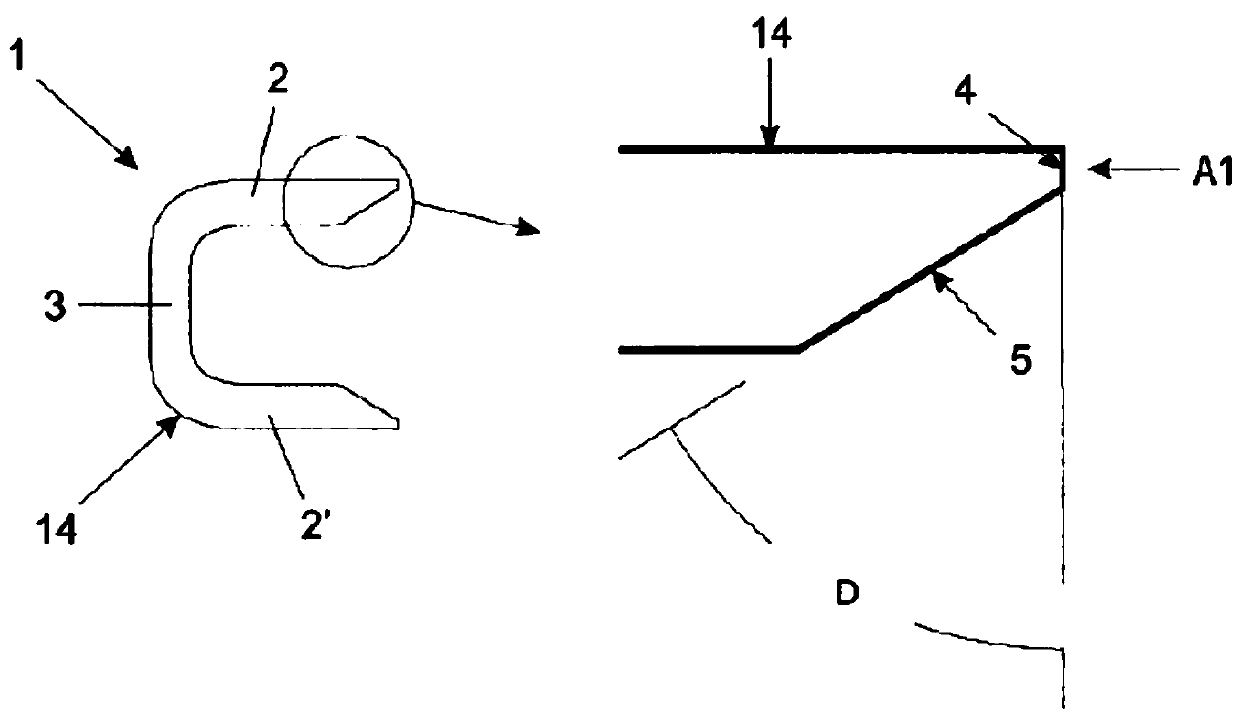
[0030] image 3 One of the segments 1 forming the body of the ring 10 is shown, comprising a cross-section having a substantially "C"-shaped form defining an upper part 2 and a lower part corresponding to the free extremities of the "C" 2', and a center portion 3 corresponding to the base of the "C". The upper part 2 and the lower part 2' are oriented towards the inner surface of the cylinder liner 20 when the ring 10 is mounted in the groove of t...


PUM

PropertyMeasurementUnit
Thicknessaaaaaaaaaa
Hardnessaaaaaaaaaa
Hardnessaaaaaaaaaa

Abstract

The present invention relates to a one piece oil control ring (10) for an internal combustion engine capable of readily conforming to a cylinder liner (20) by virtue of the excellent flexibility of the ring (10), comprising a first surface (4) substantially parallel to the internal surface of the cylinder liner, wherefrom there extends a second substantially inclined surface (5), and comprising atempered martensitic matrix capable of receiving a nitrided layer (12), having high hardness, ensuring excellent resistance to wear and, consequently, high durability of the ring.

Description

technical field [0001] The present invention relates to an oil control ring for an internal combustion engine, in particular a one-piece ring comprising a low value of tangential force exerted on the cylinder during operation of the engine, and the ring has excellent wear resistance and durability . Background technique [0002] Internal combustion engines, whether diesel cycle, Otto cycle, two-stroke or three-stroke, include at least one piston ring. Piston rings are used to seal the gap between the cylinder liner and the body of the piston, isolating the combustion chamber from the other internal parts of the engine. Piston rings are arranged radially on the base of the body of the piston, prevent combustion gases from escaping from the combustion chamber in the direction of the oil sump, and prevent engine oil from penetrating into the combustion chamber. [0003] Typically, the engine is provided with three rings located in parallel in grooves arranged in the base of t...

Claims


Application Information

Patent Timeline
IPC IPC(8): F16J9/20
CPCF16J9/206F16J9/26
Inventor 吉塞拉·阿布拉斯·马克思保罗·若泽·达·罗沙·莫尔登特保罗·罗伯特·维埃拉·德·莫赖斯
Owner MAHLE METAL LEVE
Why Eureka
Try Eureka