
Electronic assembly for transmission control module and method of making the same

一种电子组件、电子器件的技术,应用在印刷电路制造、电气元件、电固体器件等方向,能够解决不精确放置、高制造成本、使用寿命或密封性降低等问题,达到简化制造过程、低制造成本、持久防油性的效果

Active Publication Date: 2020-12-29
ROBERT BOSCH GMBH
View PDF10 Cites 0 Cited by
  • Summary
  • Abstract
  • Description
  • Claims
  • Application Information

AI Technical Summary

Problems solved by technology

[0004] Disadvantages in this regard are the transmission control module with electronic components or the electronic components are not so stable or robust and have high production costs and high production expenditures
In addition, often mechanical stresses can occur between the large individual components and the printed circuit board, as a result of which the service life or tightness of the gearbox control module or electronic components is reduced
Furthermore, often due to the thickness tolerances of the printed circuit boards it is possible to place the electronic components only very imprecisely in height, which can cause problems especially in the case of sensors

Method used


Image

  • Electronic assembly for transmission control module and method of making the same
  • Electronic assembly for transmission control module and method of making the same
  • Electronic assembly for transmission control module and method of making the same

Examples


Embodiment Construction

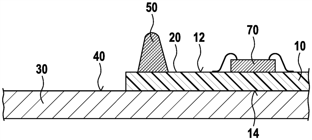
[0027] figure 1 A schematic view is shown after the first step of the method according to the invention for producing an electronic component 5 . Electronic assembly 5 may be part of a transmission control module of the vehicle.

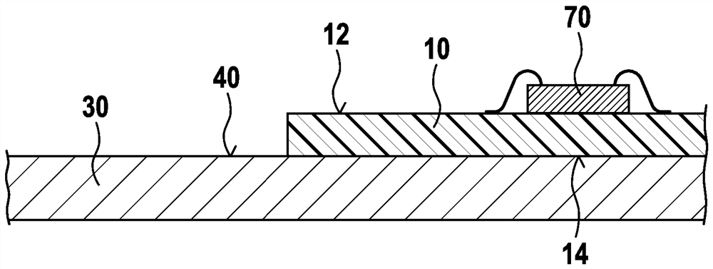
[0028] Firstly, a printed circuit board 10 (eg printed circuit board; PCB) is provided. The printed circuit board 10 has a first side 12 (in figure 1 upper center) and the second side 14 (in the figure 1 lower middle), wherein the second side 14 is opposite to the first side 12 . At least one first electronic component 70 is arranged on the first side 12 of the printed circuit board 10 . The first electronic device 70 is electrically connected to the printed circuit board 10 .

[0029] The printed circuit board 10 is arranged on the reference surface 40 . The second side 14 of the printed circuit board 10 is connected planarly to the reference surface 40 or is fastened thereto. Alternatively, the printed circuit board can also lie flat on the ...


PUM


Abstract

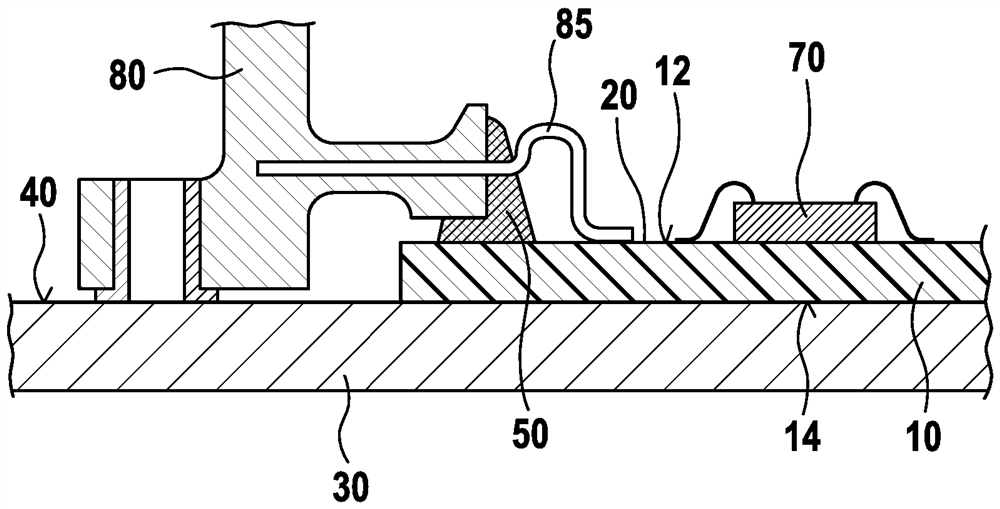
A method for producing an electronic assembly (5), in particular an electronic assembly (5) for a gearbox control module, is specified, the method comprising the steps of: providing a printed circuit board (10) having a first A side (12) and a second side (14) facing away from the first side (12) and having at least one first electronic component (70) arranged on the first side (12) of the printed circuit board (10) ; the printed circuit board ( 10 ) is at least partially arranged on the reference surface ( 40 ) with the second side ( 14 ); applying a sealing material ( 50 ) which is substantially non-flowable before age hardening to the first side ( 12), wherein the sealing material (50) is coated such that the sealing material (50) surrounds a partial area (20) of the first side (12) of the printed circuit board (10); the second device (80 ) is at least partially arranged on the reference surface (40), so that the second device (80) is partially pressed into the sealing material (50); the second device (80) is electrically connected to the printed circuit board (10); applying a covering material (60), in particular a covering material (60) that is flowable before age hardening, to the first side (12) of the printed circuit board (10) The partial area (20) surrounded by the sealing material (50) is applied to the first component (70); the sealing material (50) is age-hardened; and the covering material (60) is age-hardened.

Description

technical field [0001] The invention relates to a method for producing an electronic assembly, in particular for a transmission control module, and an electronic assembly, in particular for a transmission control module. Background technique [0002] Various electronic assemblies are known. The electronic assembly must be sealed against oil, for example if it is part of a transmission control module, since the transmission control module is in an oil environment. The electronic assembly typically includes a printed circuit board having electronic devices disposed thereon. [0003] Larger individual components, such as sensors, are partially not arranged on the printed circuit board, but are electrically connected to the printed circuit board. Since the oil often contains electrically conductive particles, electrical insulation is necessary both for the components and for the electrical connections between large individual components that are not (completely) arranged on th...

Claims


Application Information

Patent Timeline
Patent Type & Authority Patents(China)
IPC IPC(8): H05K5/00H05K3/28
CPCH05K3/284H05K2201/09909H05K2201/1031H05K5/0082Y02P70/50H01L2224/48091H01L2924/181H01L2224/48227H01L2924/00014H01L2924/00012H05K1/0203H05K1/181H05K5/065H05K2201/066H05K2201/10151H05K2203/1316H05K2203/1327H05K2203/167
Inventor P.兹魏格勒H.德林格J.霍夫曼
Owner ROBERT BOSCH GMBH
Learn More