Robot and robot system

A robot system and robot technology, applied in the field of robots and robot systems, can solve problems such as increased cost, complex structure, and high failure probability

Pending Publication Date: 2019-05-24
SEIKO EPSON CORP
View PDF5 Cites 0 Cited by
  • Summary
  • Abstract
  • Description
  • Claims
  • Application Information

AI Technical Summary

Problems solved by technology

[0005] However, in Patent Document 1, in order to photograph objects at different depths of field, it is necessary to move the arm and drive the lens mechanism to focus, so it may take time until the photograph is taken, and the cycle time of the work may become longer.
In addition, when a mechanism that drives the lens mechanism to focus is used, the structure may become complicated, the probability of failure may increase, and the cost may increase

Method used


Image

  • Robot and robot system
  • Robot and robot system
  • Robot and robot system

Examples


Embodiment 1

[0124] Figure 11 is a diagram showing a stereoscopic image of this embodiment.

[0125] Figure 11 An example of a stereoscopic image synthesized by the control device 30 is shown. The three-dimensional images are horizontally arranged and synthesized, and among the two cameras constituting the first three-dimensional camera 20a, figure 1 The image of the left camera is arranged in the left camera image portion, and the image of the right camera is arranged in the right camera image portion.

[0126] In recent years, as the image quality of cameras has increased, the size of one image has increased, and the time required for data processing and transmission / reception has increased. Therefore, although a stereoscopic image displayed using a demonstration device not shown in the figure may cause a deviation in shooting time between right and left, managing the stereoscopic image as a single image is a solution to this problem.

Embodiment 2

[0128] Figure 12 is a diagram showing a stereoscopic image of this embodiment.

[0129] The image processing unit 42 synthesizes the captured images captured by the two cameras constituting the first stereo camera 20 a into one image arranged side by side, and receives it. Thus, it is better ensured that the images of the first stereo camera 20a do not deviate in time.

[0130] exist Figure 11 In addition to the stereo image of the structure shown, in order to efficiently manage images on the system, you can also use Figure 12 Synthetic stereoscopic images of the structures shown. The synthesized image is composed of three regions: the left camera image part, the right camera image part, and the blacked-in part, and the image size is generated by the maximum size that can be captured by any camera included in the robot system 2 . The left camera image portion and the right camera image portion contained in the synthesized stereoscopic image are reduced in size compared ...


PUM


Abstract

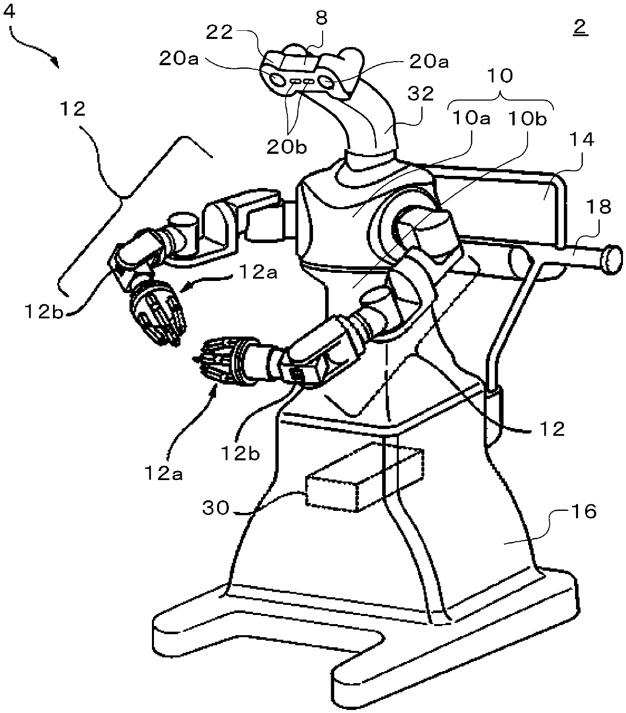
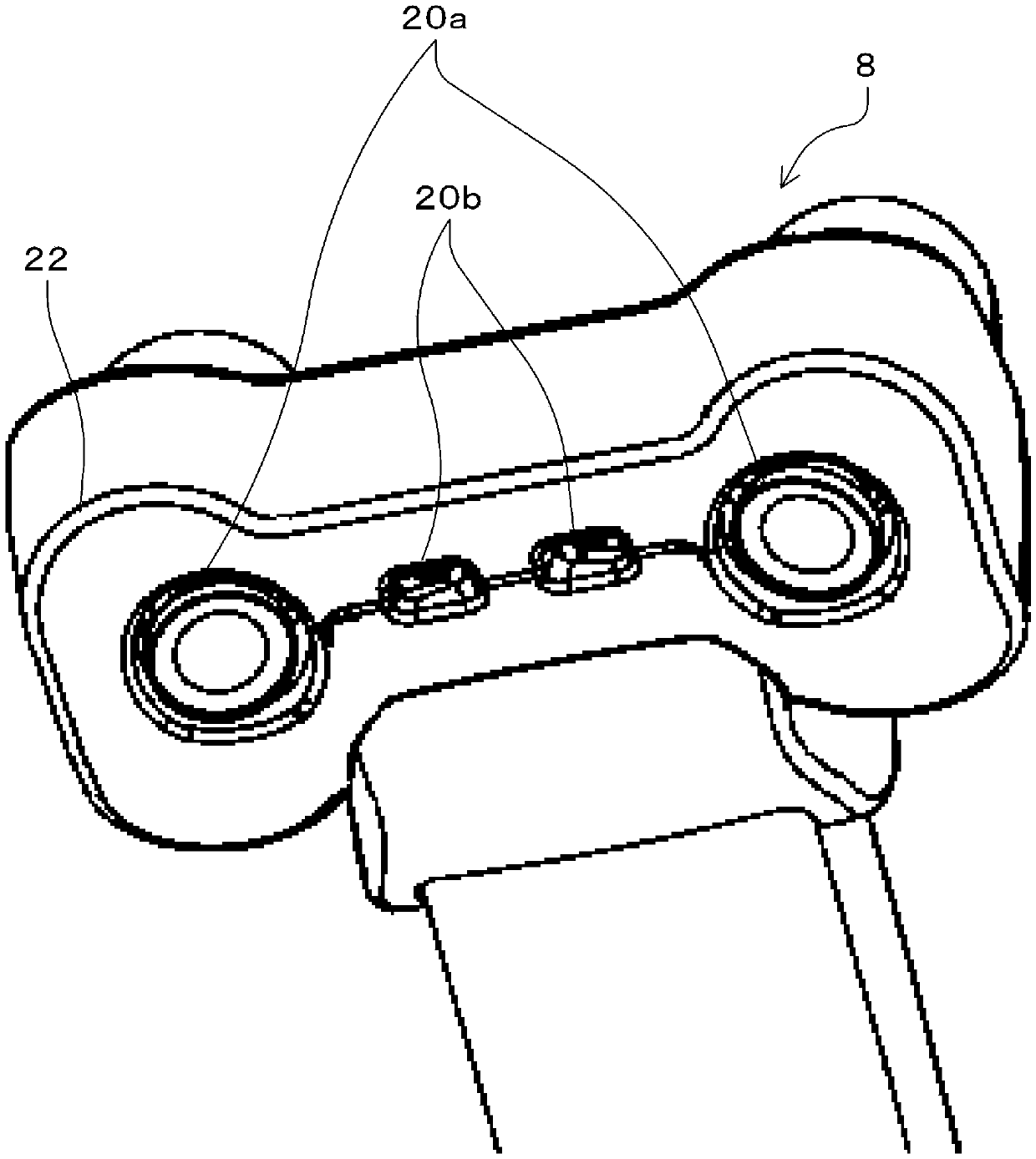
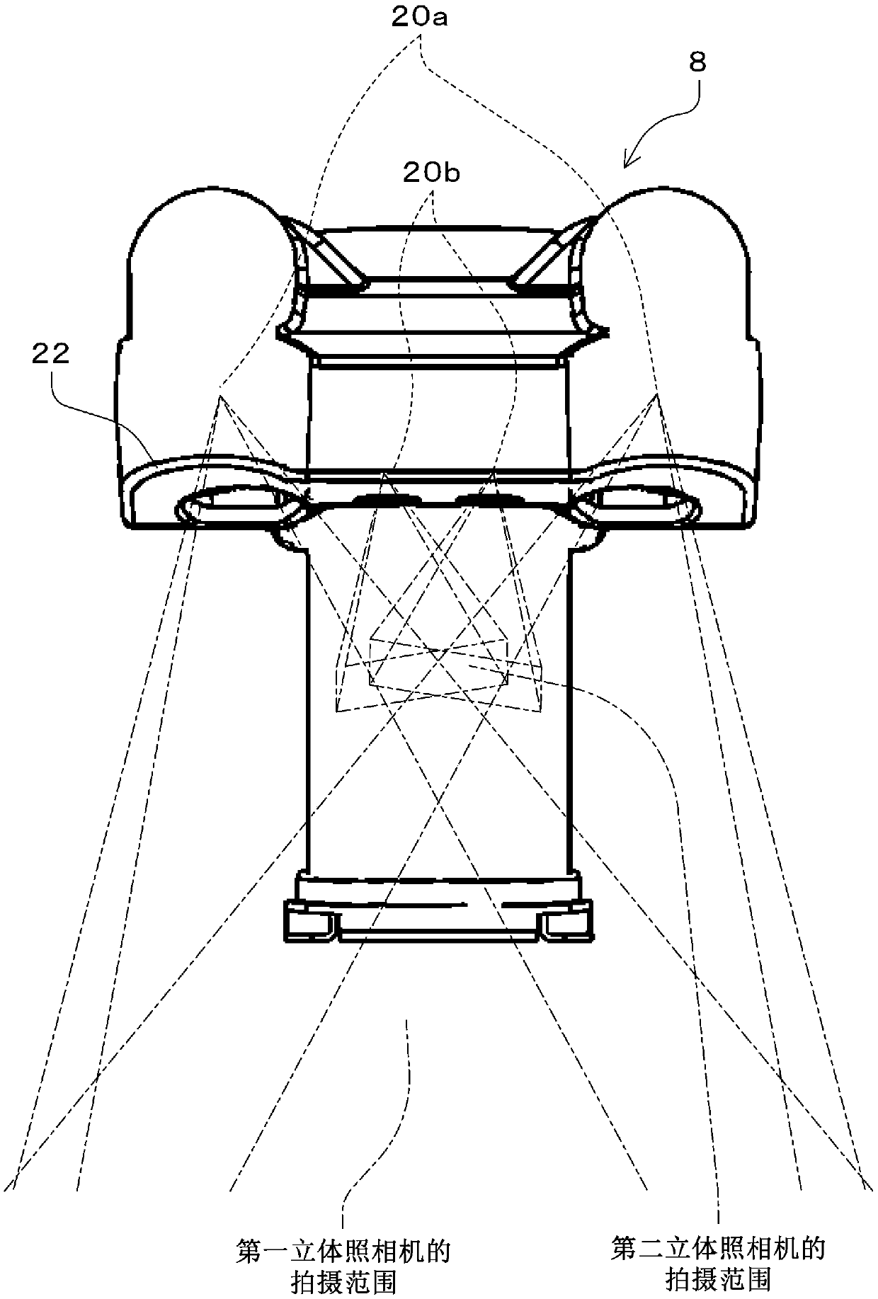
A robot includes a shoulder, an arm connected to the shoulder, an imaging device that is connected to the shoulder via a support, and an image receiver that receives a captured image captured by the imaging device, and a robot controller that controls the arm based on the captured image, and in which the imaging device is two sets of stereo cameras having different depths of field.

Description

technical field [0001] The present invention relates to robots and robotic systems. Background technique [0002] Currently, in a robot equipped with a stereo camera and multiple arms, when an object is grasped by an end effector provided at the front end of the arm and the object is moved to a position where the stereo camera can capture images, in order to image the object with high precision, It is necessary to move the object to a position accommodated by the depth of field of the stereo camera. At this time, if it is desired to zoom in further and take a high-precision image of the subject, a mechanism for physically moving the lenses attached to the respective cameras on the stereo camera to perform zooming and the like is required. [0003] In this regard, a known robot (for example, refer to Patent Document 1) is equipped with a stereo camera at the front end of the robot arm. The images passed through each lens mechanism are shot on the two shooting elements of th...

Claims


Application Information

Patent Timeline
Patent Type & Authority Applications(China)
IPC IPC(8): B25J19/00H04N13/204
CPCH04N13/239H04N13/243H04N13/156H04N2213/001H04N13/25B25J9/1697G05B2219/39076G05B2219/40425G05B2219/40604G05B2219/39371G05B19/402
Inventor 田中俊雄佐田俊甫
Owner SEIKO EPSON CORP
Why Eureka
Try Eureka