

A kind of additive manufacturing method
An additive manufacturing and powder material technology, applied in the field of additive manufacturing, can solve the problems of reducing the efficiency of equipment processing and sintering, affecting the subsequent sintering of workpieces, and sintering on the substrate, so as to improve the reusability and the mechanical properties and dimensions of the parts. Accuracy, reduce processing cost, improve the effect of warpage
- Summary
- Abstract
- Description
- Claims
- Application Information
AI Technical Summary
Problems solved by technology
Method used
Image

Examples
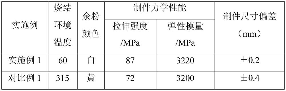
Embodiment 1
[0026] Nylon copolymer powder with a particle size of less than 500 μm and improved melt fluidity ( CM8000, the melting point of the material is 137°C), the material is spread on a stainless steel substrate with a conical hole (diameter 3mm, depth 2mm) on the upper surface, the thickness of the powder layer is 10mm, and then filled with nitrogen to reduce the oxygen content in the equipment cavity to 0.3%. Heat the substrate to 170°C to completely melt the above powder into a melt, stop heating after the melt is leveled, and cool until it is completely solidified into a solid. The powder feeding cylinder is filled with PEEK powder with a particle size range of 30-120 μm, and the equipment cavity is filled with nitrogen to reduce the oxygen content to below 0.3%. After loading the stl file, a support is generated to connect the substrate and the workpiece to be sintered. Sintering equipment The cavity does not need to be heated, so that the polymer powder material with high me...
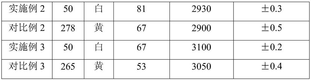
Embodiment 2
[0030] Nylon copolymer powder with particle size less than 50 μm and improved melt fluidity ( CM8000, the melting point of the material is 137°C), the material is spread on a stainless steel substrate with a conical hole (diameter 3mm, depth 2mm) on the upper surface, the thickness of the powder layer is 10mm, and then filled with nitrogen to reduce the oxygen content in the equipment cavity to 0.3%. Heat the substrate to 170°C to completely melt the above powder into a melt, stop heating after the melt is leveled, and cool until it is completely solidified into a solid. The powder feeding cylinder is filled with PA46 powder with a particle size range of 30-120 μm, and the equipment cavity is filled with nitrogen to reduce the oxygen content to below 0.3%. After loading the stl file, a support is generated to connect the substrate and the workpiece to be sintered. Sintering equipment The cavity does not need to be heated, and the high melting point polymer powder material can...
Embodiment 3
[0034] Nylon copolymer powder with a particle size of less than 500 μm and improved melt fluidity ( CM8000, the melting point of the material is 137°C), the material is spread on a stainless steel substrate with a conical hole (diameter 3mm, depth 2mm) on the upper surface, the thickness of the powder layer is 10mm, and then filled with nitrogen to reduce the oxygen content in the equipment cavity to 0.3%. Heat the substrate to 170°C to completely melt the above powder into a melt, stop heating after the melt is leveled, and cool until it is completely solidified into a solid. The powder feeding cylinder is loaded with PPS powder with a particle size range of 30-120 μm, and the equipment cavity is filled with nitrogen to reduce the oxygen content to below 0.3%. After loading the stl file, a support is generated to connect the substrate and the workpiece to be sintered. Sintering equipment The cavity does not need to be heated to realize the polymer powder material with high me...
PUM
| Property | Measurement | Unit |
|---|---|---|
| melting point | aaaaa | aaaaa |
| particle size | aaaaa | aaaaa |
| melting point | aaaaa | aaaaa |
Abstract
Description
Claims
Application Information