Leadless conductive target plate

A conductive target and leadless technology, which is applied in the direction of targets, other rubber adhesives, adhesive types, etc., can solve the problems of shooting accuracy uncertainty, lead wire disconnection, affecting target reporting work and shooting training, etc. To achieve the effect of prolonging the continuous working time and prolonging the service life

Pending Publication Date: 2019-05-24
JUNPENG SPECIAL EQUIP
View PDF0 Cites 1 Cited by
  • Summary
  • Abstract
  • Description
  • Claims
  • Application Information

AI Technical Summary

Problems solved by technology

[0003] However, the existing target boards are generally provided with lead wires at the bottom of each ring target through clamps, and then connected to the data processing module through the lead wires, and these lead wires are exposed under the target board, and t...

Method used


Image

  • Leadless conductive target plate
  • Leadless conductive target plate
  • Leadless conductive target plate

Examples


Embodiment 1

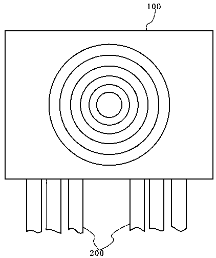
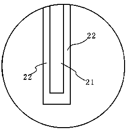
[0028] Such as Figure 1-3 As shown, this embodiment provides a leadless conductive target board, including a target 100 with several groups of conductive units 106 built in and a conductor 200 electrically connected to each conductive unit 106 and exposed to the target 100. The conductor 200 It includes a conductive cloth 21 with a width of not less than 1 cm and a waterproof insulating layer 22 sealingly covering the conductive cloth 21. The waterproof insulating layer 22 is preferably a silicone rubber layer, and the width of the conductive cloth 21 is preferably 1 cm to 2 cm.

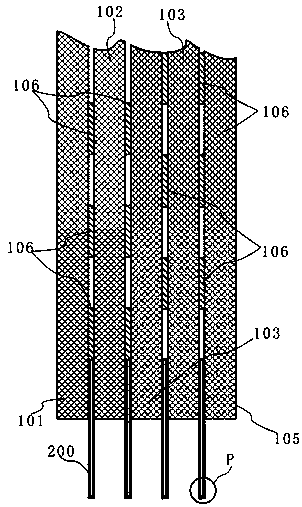
[0029] The target 100 includes five insulating plates that are bonded together in sequence, from front to back, they are insulating plate A101, insulating plate B102, insulating plate C103, insulating plate D104 and insulating plate E105, wherein the front surface of the insulating plate A101 The target surface pattern is printed, the conductive unit on the front surface of the insulating board B102...

Embodiment 2

[0032] This embodiment also provides a leadless conductive target plate, which further makes the following improvements on the basis of the technical solution described in the above-mentioned embodiment 1: Figure 4 As shown, the conductor 200 also includes a heat dissipation layer 23 and a damping adhesive layer 24, the damping adhesive layer 24 is bonded to the front end of the waterproof insulating layer 22 on the front side of the conductive cloth 21, and the heat dissipation layer 23 is embedded in the Between the damping rubber layer 24 and the waterproof insulating layer 22 .

[0033] The main function of the damping rubber layer 24 is to reduce the impact of the bullet on the conductive cloth 21, reduce the lethality of the bullet to the conductive cloth 21 or make the bullet blocked in the damping rubber layer 24, and after the bullet penetrates the damping rubber layer 24 The bullet holes on the damping adhesive layer 24 will shrink automatically, reducing the damage...


PUM

PropertyMeasurementUnit
Thicknessaaaaaaaaaa

Abstract

The invention relates to the technical field of shooting target scoring devices, in particular to a leadless conductive target plate. The leadless conductive target plate comprises a target and conductors; multiple groups of conductive units are arranged inside the target; the conductors are electrically connected with the conductive units and are exposed out of the target; each conductor comprises conductive cloth having the width not smaller than 1 cm and a waterproof insulating layer coating the conductive cloth in a sealing manner; each conductor further comprises a heat dissipation layerand a damping glue layer; each damping glue layer is bonded to the front end surface of the waterproof insulating layer on the front side of the corresponding conductive cloth; and each heat dissipation layer is embedded between the corresponding damping glue layer and the corresponding waterproof insulating layer. According to the conductive target plate, the conductors comprise the conductive cloth having the width larger than 1 cm, even if the conductors are hit by bullets, however the diameter of the bullets is smaller than the conductive cloth, so that breakage of circuits of the conductive cloth due to one-time hitting can be avoided, and the service life and the continuous working hours are prolonged; and meanwhile, compared with traditional exposed clamp type target plates, the leadless conductive target plate is higher in connection reliability and better and safer in electrical insulating property.

Description

technical field [0001] The invention relates to the technical field of shooting target reporting devices, in particular to a leadless conductive target board. Background technique [0002] In military ammunition training, target reading and target reporting are important tasks. The existing technology is to read and report targets nearby by the staff after one round of design is finished. In the existing technology, there is a double-layer electrode short-circuit sampling method. Its structure and principle are an insulating panel made of a plate-shaped insulating material, an insulating partition, an insulating back plate and a plate-shaped conductive material (plate-shaped) after the chest target map. The material is made of metal materials such as copper plates, aluminum plates, and iron plates) and the ring targets are alternately superimposed. The formed ring targets are normally open circuits. When shooting with live ammunition, as long as the metal bullet penetrates ...

Claims


Application Information

Patent Timeline
IPC IPC(8): F41J1/01C09J109/02C09J119/00C09J161/14C09J11/04
Inventor 陈江填龚才琪黄冰冰
Owner JUNPENG SPECIAL EQUIP
Why Eureka
Try Eureka