Particle light manipulation device based on ring-core coaxial helical waveguide fiber

A toroidal core, helical wave technology, applied in optical waveguides, cladding fibers, radiation/particle processing, etc., can solve problems such as low flexibility and difficult probe-type applications

Active Publication Date: 2021-04-30
GUILIN UNIV OF ELECTRONIC TECH
View PDF5 Cites 0 Cited by
  • Summary
  • Abstract
  • Description
  • Claims
  • Application Information

AI Technical Summary

Problems solved by technology

Although the system can achieve stable three-dimensional capture and rotation of particles, the system requires expensive and large spatial optical devices such as spatial light modulators, and its flexibility is not high, making it difficult to implement probe applications
Therefore, the researchers used the few-mode optical fiber tapered fiber-end probe to realize the three-dimensional capture and direction control of yeast cells (Jounal of Lightwave Technol, 2014, 32(6):1098-103), but this system cannot realize the Stable rotation function
In addition, Chen et al. also used the optical fiber LP21 mode to realize the rotation operation of biological cells (Journal of Optics, 2014, 16(12): 125302), but this system cannot form a stable three-dimensional capture of cells

Method used


Image

  • Particle light manipulation device based on ring-core coaxial helical waveguide fiber
  • Particle light manipulation device based on ring-core coaxial helical waveguide fiber
  • Particle light manipulation device based on ring-core coaxial helical waveguide fiber

Examples


Embodiment Construction

[0026] The present invention is described in more detail below in conjunction with accompanying drawing example:

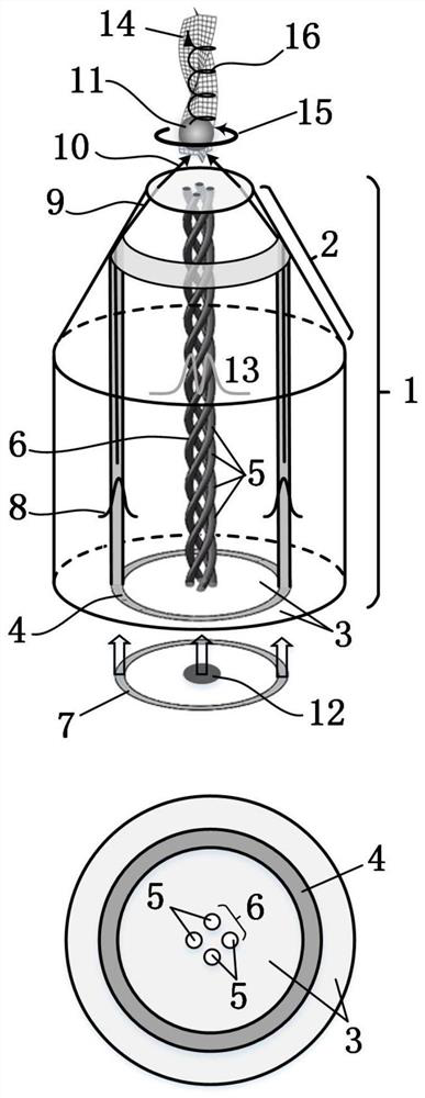
[0027] combine figure 1 , the embodiment of the present invention is composed of a ring-core coaxial helical waveguide fiber 1, and the fiber end of the fiber is ground to form a truncated cone 2 at the fiber end; the ring-core coaxial helical waveguide fiber 1 includes a cladding 3, a ring core 4 and A central core 6 consisting of a number of helical waveguides 5. On the one hand, when the ring light 7 is input to the ring-core coaxial helical waveguide fiber 1, the ring-core guided mode 8 will be excited in the ring core 4, and then pass through the frustum of the fiber end 2 (the separation between the cladding and the external medium). total internal reflection occurs at the interface), the reflected light wave 9 is diffracted in the cladding of the fiber end and transmitted to the end face of the fiber end, and then refracted at the fiber end to form a stron...


PUM


Abstract

The invention is a particle light manipulation device based on a ring-core coaxial helical waveguide fiber. It is characterized in that: the device is composed of a ring-core coaxial helical waveguide fiber 1, and the fiber end of the fiber is ground to form a truncated cone 2 at the fiber end; the ring-core coaxial helical waveguide fiber 1 includes a cladding 3, a ring core 4 and a central core 6 consisting of multiple helical waveguides 5. On the one hand, the device can emit a strong focused annular light field 10 through the fiber end of the ring-core coaxial helical waveguide fiber 1, realize stable three-dimensional capture of the particle 11 near the focal point outside the fiber end, and realize the positioning and positioning of the particle 11. On the other hand, the fixed-axis rotation 15 and rotational ejection 16 of the particles 11 can also be realized by controlling the energy of the phase vortex beam 14 emitted from the helical fiber core. The invention can be used in the fields of optical information transmission, optical micromanipulation, microscopic imaging, light manipulation of tiny particles such as medicine particles, and application of optical fiber integrated devices.

Description

[0001] (1) Technical field [0002] The invention relates to a particle light manipulation device based on a ring-core coaxial helical waveguide fiber, which can be used in the fields of optical information transmission, optical micromanipulation, microscopic imaging, light manipulation of tiny particles such as drug particles, and application of optical fiber integrated devices. . [0003] (2) Background technology [0004] The momentum of an electromagnetic field has two components: linear momentum and angular momentum. There are two types of angular momentum: spin angular momentum and orbital angular momentum. In 1992, Allen discovered that the light field has orbital angular momentum, which led to the further study of vortex beams. Since the vortex beam carries orbital angular momentum, its magnitude is Therefore, when the vortex beam is irradiated on the particles, the orbital angular momentum carried by the photons is directly transferred to the particles in micron an...

Claims


Application Information

Patent Timeline
Patent Type & Authority Patents(China)
IPC IPC(8): G02B6/02G21K1/00
Inventor 苑立波邓洪昌吕金超
Owner GUILIN UNIV OF ELECTRONIC TECH
Why Eureka
Try Eureka