inspection target defect detection method based on feature point detection and an SVM classifier
A feature point detection and target defect technology, applied in the field of computer vision, to achieve the effect of high environmental adaptability, reduced detection error, and low computational complexity
- Summary
- Abstract
- Description
- Claims
- Application Information
AI Technical Summary
Problems solved by technology
Method used
Image
Examples
Embodiment 1
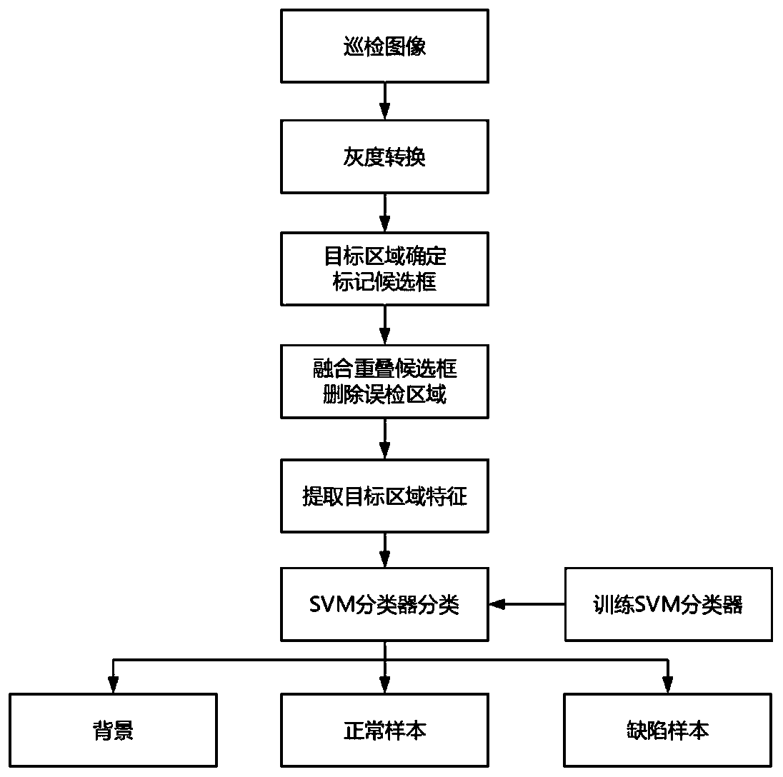
[0114] In this embodiment, the detection method is used to detect the missing parts of the simulation equipment, wherein the detection target selected in this embodiment is a nut, and the simulation equipment is completed by embedding studs on the foam board and randomly installing nuts on the studs .
[0115] Use the above steps to detect the analog device, the detection steps are as follows:
[0116] Step A: Obtain the inspection target image captured in real time, and perform grayscale value transformation on it, and convert the image from RGB space to grayscale space;
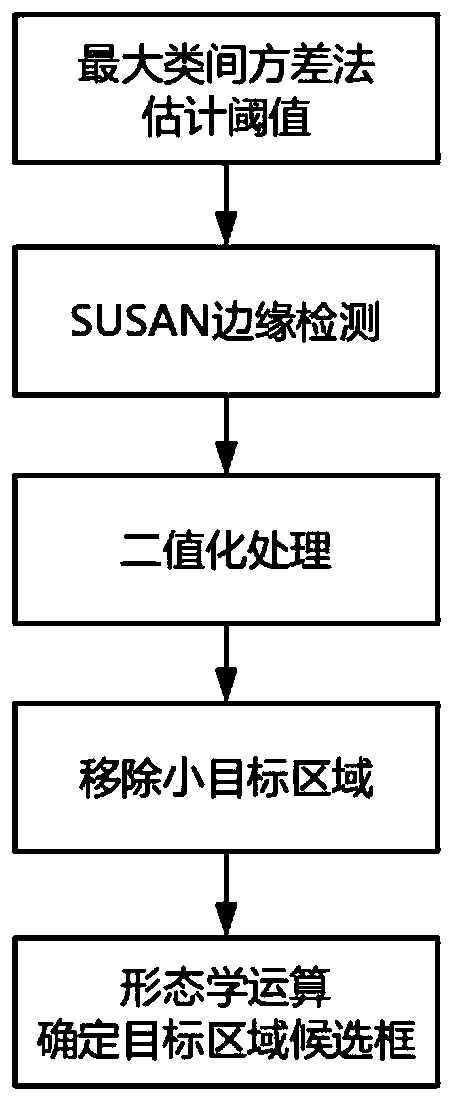
[0117] Step B: use the maximum inter-class variance method and the SUSAN edge detection method to process the converted inspection map to determine the candidate area of the target to be inspected;
[0118] Step C: Filter and fuse the candidate regions according to the shape features of the target to be detected, so as to delete the falsely detected target regions;
[0119] Step D: Extract LBP and LPQ f...
Embodiment 2
[0127] In this embodiment, the detection method is used to detect missing parts of the field equipment, wherein the detection target selected in this embodiment is the handwheel. And the detection steps are the same as those in Example 1.
[0128] After the image collected in this embodiment is processed by the step A, it is converted from an RGB image to a grayscale image. After the conversion, the target area in the image is selected using the maximum inter-class variance method and the SUSAN edge detection method, and the processed image Image feature edge connectivity areas such as Figure 6 as shown in (a);
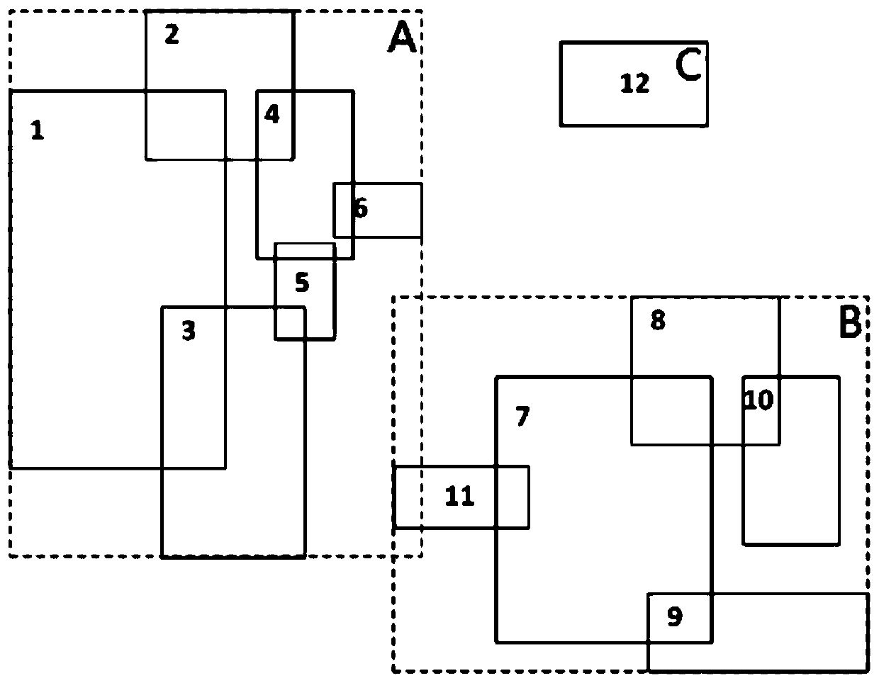
[0129] After the selection is completed, mark the selected target areas with the circumscribed candidate boxes, and the marking results are as follows Figure 6 as shown in (b);
[0130] After the candidate frame marking is completed, the overlapped candidate frames are fused by bringing the overlap rate into the matrix calculation. The result after fusion is as f...
PUM
 Abstract
Description
Claims
Application Information
 - R&D
- Intellectual Property
- Life Sciences
- Materials
- Tech Scout
- Unparalleled Data Quality
- Higher Quality Content
- 60% Fewer Hallucinations
Browse by: Latest US Patents, China's latest patents, Technical Efficacy Thesaurus, Application Domain, Technology Topic, Popular Technical Reports.
© 2025 PatSnap. All rights reserved.Legal|Privacy policy|Modern Slavery Act Transparency Statement|Sitemap|About US| Contact US: help@patsnap.com


