Supercharge Your Innovation With Domain-Expert AI Agents!

LTCC (Low Temperature Co-fired Ceramic)-based one-split-to-three bandpass filtering power divider

A band-pass filter and band-pass filtering technology, applied in the microwave field, can solve problems such as small size, poor out-of-band suppression, and insufficient bandwidth, and achieve small input-output VSWR, good isolation between ports, and good port matching Effect

Inactive Publication Date: 2019-05-24
NANJING UNIV OF SCI & TECH
View PDF3 Cites 0 Cited by
  • Summary
  • Abstract
  • Description
  • Claims
  • Application Information

AI Technical Summary

Problems solved by technology

[0003] In 2010, P. Cheong proposed to use a resonant circuit with a band-pass response to replace the quarter-wavelength converter in the traditional Wilkinson power divider. This type of structure has a small size and high isolation, but the out-of-band suppression is poor.
In 2011, Garcia proposed a filter power splitter in which the filter and the power splitter are cascaded together in the article. Although the structure is relatively simple, the size is large
In the past ten years, scholars have gradually begun to pay attention to the research on filter power dividers. At present, there are still many problems in this technology, such as large size and insufficient bandwidth.

Method used


Image

  • LTCC (Low Temperature Co-fired Ceramic)-based one-split-to-three bandpass filtering power divider
  • LTCC (Low Temperature Co-fired Ceramic)-based one-split-to-three bandpass filtering power divider
  • LTCC (Low Temperature Co-fired Ceramic)-based one-split-to-three bandpass filtering power divider

Examples


Embodiment

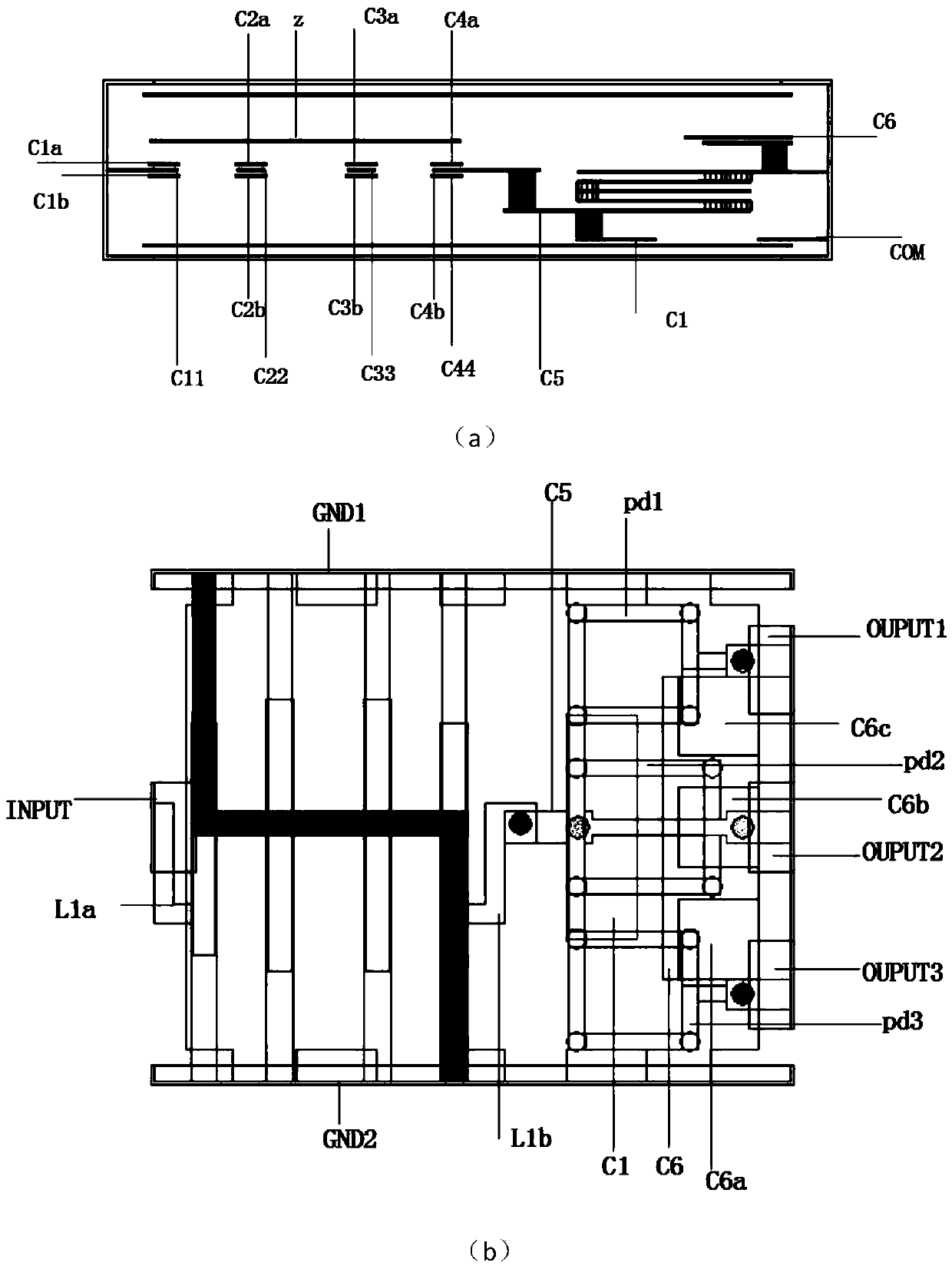
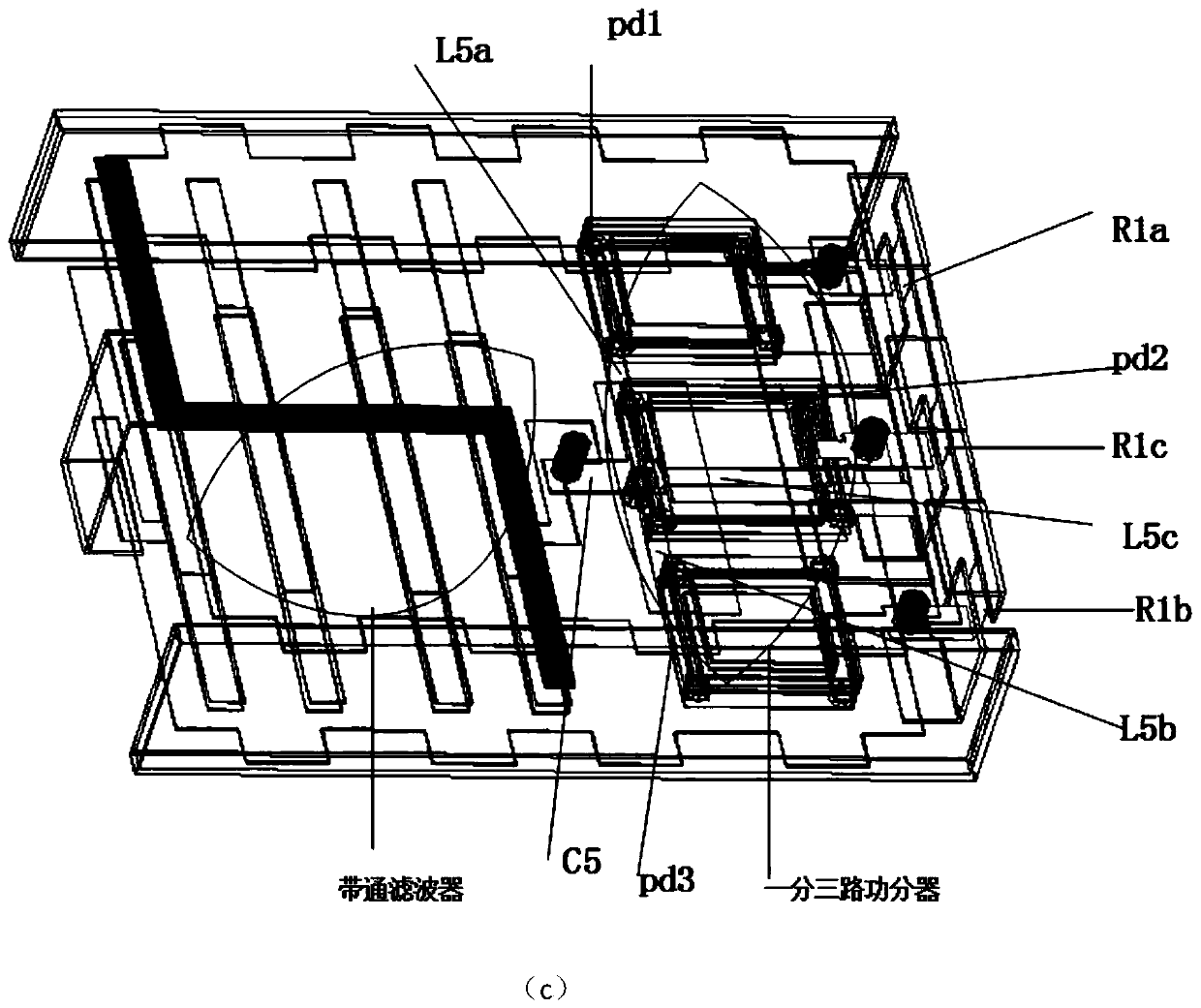
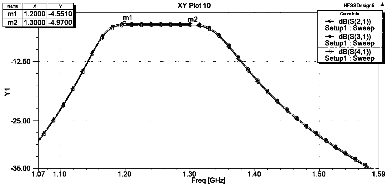
[0029] The size of the LTCC-based one-point three-way bandpass filter power divider of the present invention is only 3.2mm×4mm×0.89mm, and the working frequency is 1.2GHz~1.3GHz. Figure 2 to Figure 6It can be seen that the first output port (OUTPUT1) of the first chip resistor (R1a) with a surface mount characteristic impedance of 50 ohms, and the second port of the third chip resistor (R1c) with a surface mount characteristic impedance of 50 ohms The output waveform of the output port (OUTPUT2) and the third output port (OUTPUT3) of the second chip resistor (R1b) with a surface mount characteristic impedance of 50 ohms is basically the same, the passband is relatively flat, and the port insertion loss is less than 0.5dB. The output port isolation is better than 28dB, the return loss of the output port is better than 27dB, the return loss of the first input port (INPUT) with a characteristic impedance of 50 ohms is better than 23dB, and the output phases of the output ports ar...


PUM


Abstract

The invention discloses an LTCC (Low Temperature Co-fired Ceramic)-based one-split-to-three bandpass filtering power divider. The LTCC (Low Temperature Co-fired Ceramic)-based one-split-to-three bandpass filtering power divider includes a bandpass filter and a one-split-to-three power divider; the bandpass filter comprises a first input port, a first input inductor, four stages of parallel resonant units, a first output inductor, and a z-shaped inter-stage coupling strip line, wherein the four stages of parallel resonant units are connected with one another sequentially; the one-split-to-threepower divider is composed of a compact three-dimensional integrated structure; and the first output inductor of the passband filter is connected with the input capacitor plate of the power divider, so that the one-split-to-three bandpass filtering power divider can be formed. According to the LTCC (Low Temperature Co-fired Ceramic)-based one-split-to-three bandpass filtering power divider of theinvention, three-dimensional integration is realized through the low temperature co-fired ceramic (LTCC) process technology, and therefore, the miniaturization of the power divider is realized. The power divider of the invention has the advantages of flatness in passband, the consistency of power and phases of the output signals of three output ports, high port matching performance, good isolationbetween ports and high stability, and can be widely applied to communication systems such as communication system radio frequency front ends and mobile terminal systems.

Description

technical field [0001] The invention relates to an LTCC-based one-to-three band-pass filter power splitter, which belongs to the field of microwave technology. Background technique [0002] With the continuous development of wireless radio frequency communication technology, microwave radio frequency circuits are more and more widely used. As a key part of microwave circuits, the performance requirements for filters and power splitters are also getting higher and higher. The power divider is a multi-port passive microwave network used to distribute or synthesize signals, mainly used in microwave power amplification and linearization circuits. From the mid-1950s to the 1960s, Wilkinson power dividers appeared. Because of their simple structure and the output ports meeting the requirements of both isolation and matching, they are more widely used. With the rapid development of modern communication technology, the traditional Wilkinson structure is far from meeting the require...

Claims


Application Information

Patent Timeline
IPC IPC(8): H01P5/16H01P1/203
Inventor 方洁曹小芝常钰敏杨冕赵子豪戴永胜
Owner NANJING UNIV OF SCI & TECH
Features
  • R&D
  • Intellectual Property
  • Life Sciences
  • Materials
  • Tech Scout
  • Unparalleled Data Quality
  • Higher Quality Content
  • 60% Fewer Hallucinations
Learn More