DC micro-grid system and variable droop coefficient control method thereof

A DC microgrid and DC converter technology, which is applied in the direction of DC network circuit devices, electrical components, circuit devices, etc., can solve the problems of complexity, unsatisfactory control effect, and unsatisfactory shunt accuracy.

Active Publication Date: 2019-05-24
UNIV OF ELECTRONIC SCI & TECH OF CHINA
View PDF7 Cites 12 Cited by
  • Summary
  • Abstract
  • Description
  • Claims
  • Application Information

AI Technical Summary

Problems solved by technology

However, when using this method, the output voltage of the DC converter with the smallest line resistance in the DC microgrid will be lower than the set reference value
[0005] Some of the above methods have unsatisfactory shunt acc

Method used


Image

  • DC micro-grid system and variable droop coefficient control method thereof
  • DC micro-grid system and variable droop coefficient control method thereof
  • DC micro-grid system and variable droop coefficient control method thereof

Examples


Embodiment Construction

[0061] The technical scheme of the present invention will be further explained below in conjunction with the drawings.

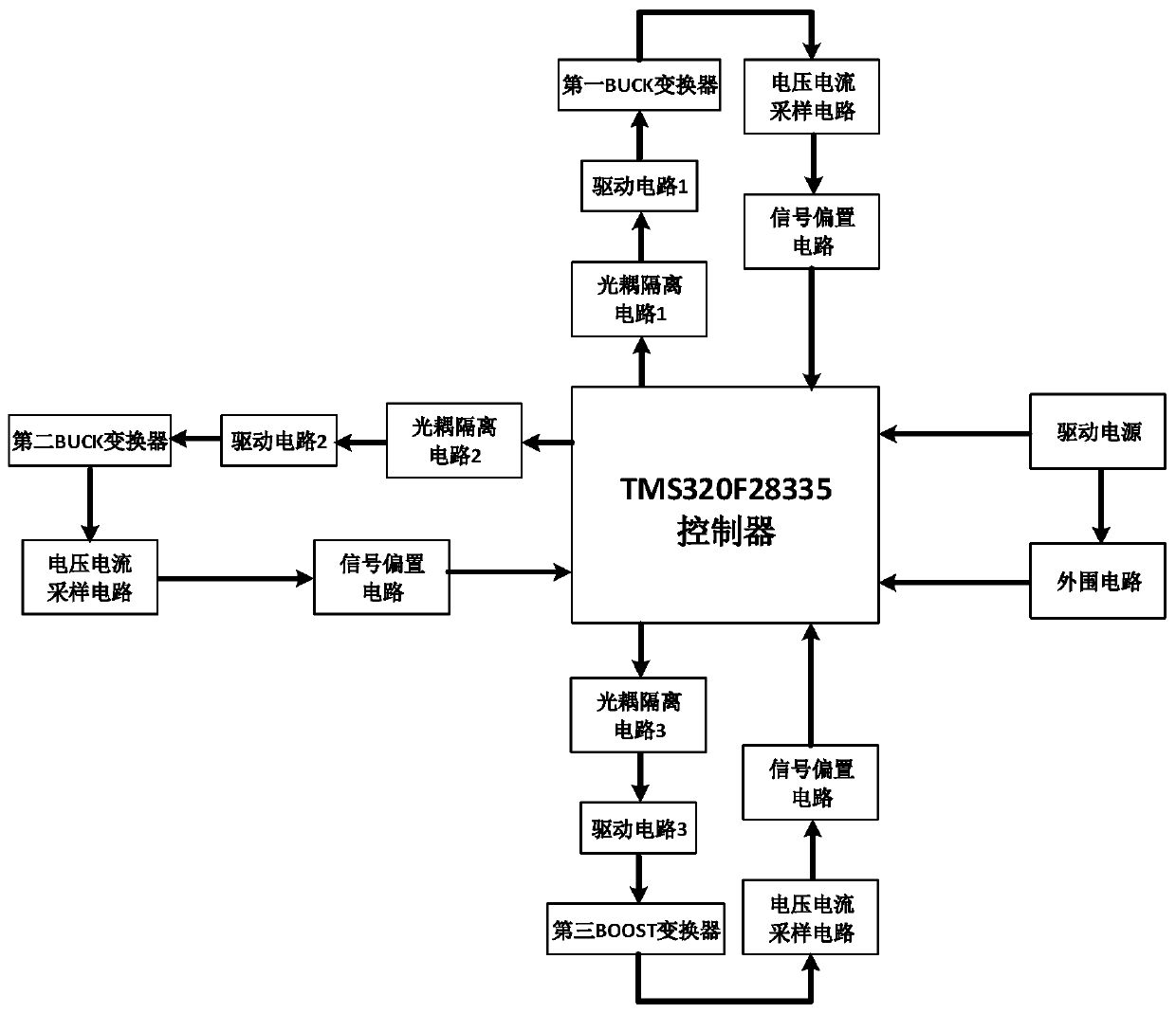
[0062] Such as figure 1 As shown, the DC microgrid system includes three converter units, two resistive loads, a TMS320F28335 controller and its auxiliary circuits. The first converter unit includes the first distributed power supply, the first BUCK converter, the first line resistance, the first static switch (to control the converter access and cut out), the switch tube drive circuit, the output voltage sampling circuit, and the output current sampling Circuit. The second converter unit includes a second distributed power supply, a second BUCK converter, a second line resistance, a second static switch (control converter access and cut out), a switch tube drive circuit, an output voltage sampling circuit, and an output current sampling Circuit. The third converter unit includes a third distributed power supply, a third BOOST converter, a third line resista...


PUM


Abstract

The invention discloses a DC micro-grid system and a variable droop coefficient control method thereof. The DC micro-grid system comprises three converter units, two resistive loads, a TMS320F28335 controller and its accessory circuit. The variable droop coefficient control method, compared with the conventional droop control, incorporates voltage recovery control and droop coefficient correctioncontrol. The method performs voltage compensation control on the output voltage minimum value, achieves a control objective that the converter output voltage minimum value is the same as a set reference value, and solves the large deviation of the conventional droop control DC bus voltage and the set voltage reference value. The method fixes the droop coefficient of one converter, and obtains thedroop coefficient compensation terms of the remaining converters by the droop coefficient correction control. The droop coefficient reference value is superimposed onto the droop coefficient compensation terms so as to form a corrected droop coefficient. Then the droop control is performed, thereby achieving a control objective that the converters equally distribute the load current under the condition that the line resistances have a large difference, and solving the problem that the shunt accuracy decreases when the line resistances of the converters are inconsistent.

Description

Technical field [0001] The invention belongs to the field of DC microgrid control of electric power system, and relates to an improved droop control method, in particular to a variable droop coefficient control method based on output voltage compensation control and droop coefficient correction control and a microgrid controlled by the method system. Background technique [0002] With the integration of a large number of renewable energy sources, the concept of microgrid was proposed. Microgrids can be divided into AC microgrids and DC microgrids. Compared with the AC microgrid, the DC microgrid has attracted more and more attention due to its lower control complexity, higher reliability and higher energy transmission efficiency. A key issue in the DC microgrid is how to coordinate and control the DC converters, so as to realize the load current equally or proportionally. The current distribution strategies proposed at present mainly include average current control, master-sla...

Claims


Application Information

Patent Timeline
IPC IPC(8): H02J1/00
CPCY02E60/60
Inventor 韩杨李路桥宁星王丛岭杨平熊静琪
Owner UNIV OF ELECTRONIC SCI & TECH OF CHINA
Why Eureka
Try Eureka