Method and device for setting critical gain of power system stabilizer

A power system, critical gain technology, applied in the direction of reducing/preventing power oscillation, etc., can solve the problems that the effect does not achieve its due effect, the critical gain test error is large, etc., to improve the dynamic stability and temporary stability level, ensure the suppression effect, The effect of reducing errors

Active Publication Date: 2019-05-24
ELECTRIC POWER RESEARCH INSTITUTE, CHINA SOUTHERN POWER GRID CO LTD +1
View PDF7 Cites 6 Cited by
  • Summary
  • Abstract
  • Description
  • Claims
  • Application Information

AI Technical Summary

Problems solved by technology

However, in the actual on-site PSS critical gain test, due to various disturbances on site, there is a problem of how to judge the occurrence of continuous oscillation
In the actual PSS critical gain measurement work for a long time, for the sake of safety, once the rotor voltage fluctuation is observed in the critical gain test, it is considered to have reached the critical gain, and there is still a huge gap from the real critical gain. The result is quite conservative. The critical gain The test error is extremely large, resulting in the effect of PSS not reaching its intended effect

Method used


Image

  • Method and device for setting critical gain of power system stabilizer
  • Method and device for setting critical gain of power system stabilizer
  • Method and device for setting critical gain of power system stabilizer

Examples


Embodiment Construction

[0037] The following will clearly and completely describe the technical solutions in the embodiments of the present invention with reference to the accompanying drawings in the embodiments of the present invention. Obviously, the described embodiments are only some, not all, embodiments of the present invention. Based on the embodiments of the present invention, all other embodiments obtained by persons of ordinary skill in the art without creative efforts fall within the protection scope of the present invention.

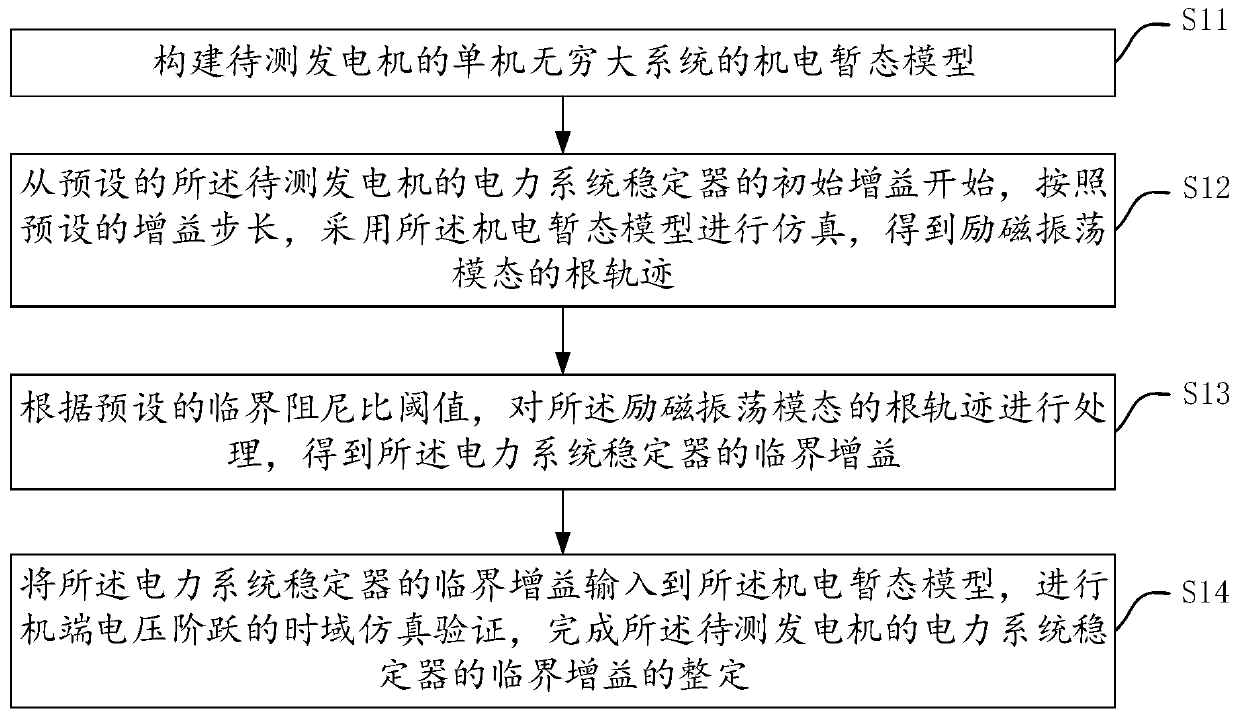
[0038] see figure 1 , is a schematic flowchart of a critical gain tuning method for a power system stabilizer provided by an embodiment of the present invention, including:

[0039] S11. Construct an electromechanical transient model of a single machine infinite system of the generator to be tested.

[0040] It can be understood that the stand-alone infinite system (SMIB) may include a generator to be tested, a step-up transformer, a transmission line, and an infi...


PUM


Abstract

The invention discloses a method and device for setting the critical gain of a power system stabilizer. The method comprises steps of constructing an electromechanical transient model for the single-machine infinite system of a generator to be tested; performing simulation by using electromechanical transient model according to a preset gain step from the preset initial gain of the power system stabilizer of the generator to be tested, so as to obtain the root trajectory of an excitation oscillation mode; according to a preset critical damping ratio threshold, processing the root trajectory ofthe excitation oscillation mode so as to obtain the critical gain of the power system stabilizer; inputting the critical gain of the power system stabilizer to the electromechanical transient model,performing time-domain simulation verification of a terminal voltage step so as to set the critical gain of the power system stabilizer of the generator to be tested. The method can reduce the actually measured error of the critical gain, set the gain value of the power system stabilizer, and further ensures the safe and stable operation of the power system.

Description

technical field [0001] The invention relates to the technical fields of power generation control and power system stability control, in particular to a critical gain setting method and device for a power system stabilizer. Background technique [0002] At present, the power system stabilizer (PSS), which is an additional damping control of the excitation system, is the most widely used, most economical and effective measure to suppress the low-frequency oscillation of the power system in the world. The effect of PSS on suppressing low-frequency oscillation depends on the PSS model and parameters. In terms of PSS parameter setting, according to the phase compensation method, the additional damping torque generated by PSS depends not only on the compensation phase determined by the setting parameters of its lead-lag link, but also on the PSS Gain setting value size. [0003] According to the requirements of relevant guidelines, the current PSS gain setting method mainly adopt...

Claims


Application Information

Patent Timeline
Patent Type & Authority Applications(China)
IPC IPC(8): H02J3/24
Inventor 陈刚梅勇
Owner ELECTRIC POWER RESEARCH INSTITUTE, CHINA SOUTHERN POWER GRID CO LTD
Why Eureka
Try Eureka