Sound production device, display system and sound production method of sound production device

A technology of a sounding device and a sounding unit, which is applied in stereophonic systems, sounding devices, frequency/direction characteristic devices, etc., and can solve problems such as poor sounding orientation effect and the inability of the sounding direction of the sounding unit to follow the direction of the target.

Inactive Publication Date: 2019-05-24
HEFEI BOE OPTOELECTRONICS TECH +1
View PDF8 Cites 5 Cited by
  • Summary
  • Abstract
  • Description
  • Claims
  • Application Information

AI Technical Summary

Problems solved by technology

[0004] The present invention aims at the problem that the existing sounding orientation effect is poor, and the sounding direction of the sounding unit cannot follow the change of the target direction, and provides a sounding device, a display system and a sounding device with good directional effect, which can automatically change the sounding direction following the change of the target direction Sounding method of the device

Method used


Image

  • Sound production device, display system and sound production method of sound production device
  • Sound production device, display system and sound production method of sound production device
  • Sound production device, display system and sound production method of sound production device

Examples


Embodiment Construction

[0053] In order to enable those skilled in the art to better understand the technical solutions of the present invention, the present invention will be further described in detail below in conjunction with the accompanying drawings and specific embodiments.

[0054] Glossary

[0055] In this application, unless otherwise specified, the following technical terms shall be interpreted according to the following explanations:

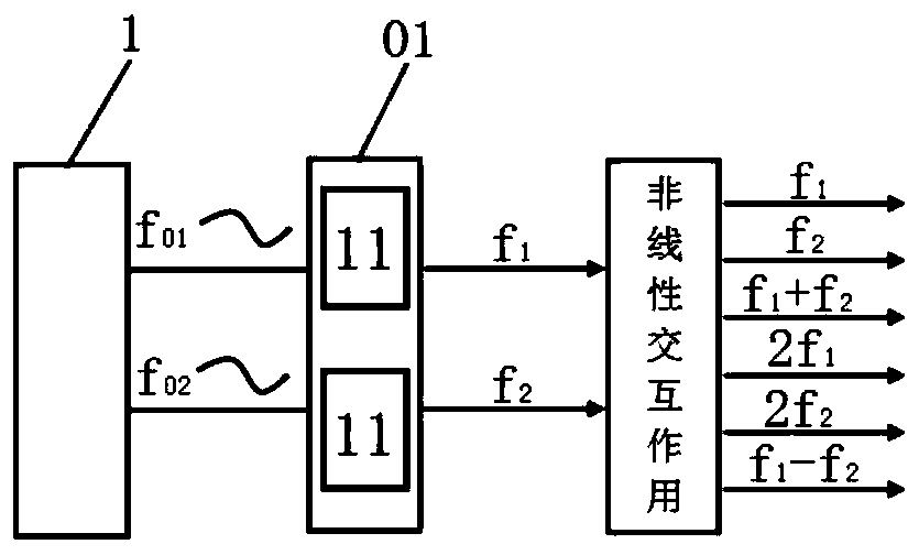
[0056] The target area refers to the area (such as the user's position) where it is desired to generate a difference frequency sound wave, and by adjusting the sounding direction of two ultrasonic transducers, they can generate a difference frequency sound wave in a certain area. The present invention is to control two ultrasonic transducers. The transducer produces a difference frequency sound wave in the target area.

[0057] The target direction refers to the two ultrasonic transducers of a sounding unit. When one of them emits the first ultrasonic wa...


PUM


Abstract

The invention provides a sound production device, a display system and a sound production method of the sound production device, belongs to the technical field of display, and can solve the problems that the sound production orientation effect of the existing sound production device is poor and the sound production orientation cannot be automatically changed along with the change of a target direction. The sound production device comprises a plurality of ultrasonic transducers, the ultrasonic transducers can form at least one sound production unit, and each sound production unit comprises twoultrasonic transducers; One ultrasonic transducer in each sound production unit is used for transmitting first ultrasonic waves, and the other ultrasonic transducer in each sound production unit is used for transmitting second ultrasonic waves; The sound production control unit is configured to determine a target direction and output a direction instruction to the motion unit according to the target direction; And the motion unit is configured to adjust the sound production direction of the ultrasonic transducers according to the direction instruction, so that the two ultrasonic transducers ofeach sound production unit generate sound towards the target direction and then generate difference frequency sound waves in an audible frequency range in the target area.

Description

technical field [0001] The invention belongs to the field of display technology, and in particular relates to a sounding device, a display system and a sounding method. Background technique [0002] The traditional sound generating device directly vibrates the air molecules through the horn to produce sound, and the sound wave propagates in all directions, and the sound field of the sound wave is approximately spherical. However, some of the directions in which the sound waves from the sound generating device can be received are not the target direction (an area where the user expects to receive the sound waves). Therefore, the traditional sound emitting device has at least the following problems: on the one hand, noise pollution is generated in non-target directions; on the other hand, it is not conducive to protecting the personal privacy of users. [0003] Directional sound generation can solve the above problems very well. The directional sound generation here means tha...

Claims


Application Information

Patent Timeline
Patent Type & Authority Applications(China)
IPC IPC(8): H04R1/20
CPCG10K11/352H04R2217/03H04R2201/401H04R2430/20H04R2499/15H04R1/403H04R2201/025H04R3/12H04R5/02H04S7/303H04R2203/12G06V40/172G10K11/34H04S2400/11G06V40/166
Inventor 张国君黄炯李朋韩乐乐祝政委
Owner HEFEI BOE OPTOELECTRONICS TECH
Why Eureka
Try Eureka