Super electrical battery

An electrode, nano-scale technology, applied in battery electrodes, secondary batteries, circuits, etc., can solve the problems of high manufacturing cost of energy storage capacity, and achieve the effect of low manufacturing cost and ultra-high capacity

Inactive Publication Date: 2019-05-24
李宇镛
View PDF3 Cites 0 Cited by
  • Summary
  • Abstract
  • Description
  • Claims
  • Application Information

AI Technical Summary

Problems solved by technology

Conventional energy storage devices are limited by many issues, one of which is energy storage capacity and high manufacturing cost

Method used


Image

  • Super electrical battery
  • Super electrical battery
  • Super electrical battery

Examples


Embodiment Construction

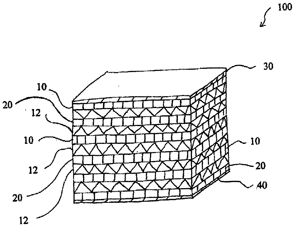
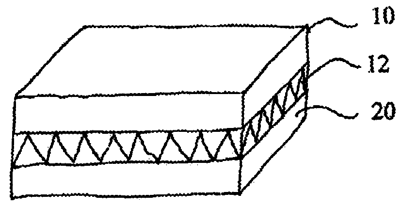
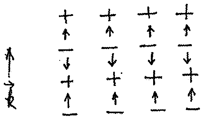
[0056] Figure 1 to Figure 6 A multilayer structure of an electrical energy storage device according to the invention is shown. Figure 7 and Figure 8 is a schematic circuit diagram for charging and discharging an electrical energy storage device. Figure 9 to Figure 12 Operation of an electrical energy storage device is shown. Figure 13 It is shown how to obtain a multilayer structure. Figure 14 Dipole-dipole interactions between excitonic dipoles and ionic dipoles are shown. Figure 15 Propagation of the dipole field to the empty state is shown. Figure 16 The transition to an exciton bipolaron is shown. Figure 17 The antiferroelectric transition according to the invention is shown. Figure 18 A linear chain of dipoles is shown. Figure 19 A bilayer structure is shown.

[0057] The electrical energy storage device 100 includes a first conductor layer 10 , a second conductor layer 20 , a positive electrode 30 and a negative electrode 40 .

[0058] The first conduct...


PUM

PropertyMeasurementUnit
weightaaaaaaaaaa
diameteraaaaaaaaaa
thicknessaaaaaaaaaa

Abstract

An electric energy storage device is provided, which includes first and second conductor layers, and positive and negative electrodes. Each of the first and second conductor layers has both surfaces coated with ionic or dipole material. A bilayer is comprised of the first conductor layer and the second conductor layer and ionic material layer sandwiched between them. A multilayer structure is comprised of millions of bilayers which are stacked together one by one. The positive electrode is attached to the first conductor layer and the negative electrode is attached to the last conductor layer.The first conductor layer is stacked on top of the second conductor layer with a nanometer-scale interval and with the ionic material layer inbetween, forming a bilayer structure and a quantum heterostructure. The first and second conductor layers form a bilayer configured to store electrical energy in the bilayer in a form of binding energy.

Description

[0001] related application [0002] This application is a PCT application claiming priority to US Patent Application No. 15 / 291,019 "SUPERELECTRICAL BATTERY" filed on October 11, 2016. Background technique [0003] Ideally, methods would be developed for storing electrical energy generated from various sources so that they can be used when needed. [0004] The invention relates to an electric energy storage device. More specifically, the present invention relates to an electrical energy storage device with ultra-high capacity. The present invention discloses a novel physical mechanism that is completely different from that of conventional batteries and capacitors. This presents an innovative approach that has aroused great interest. [0005] To compete with less expensive fossil fuel power systems, batteries should be cheap so that they can be made from earth-abundant materials, and they should be able to store large amounts of energy per weight. [0006] An improved metho...

Claims


Application Information

Patent Timeline
Patent Type & Authority Applications(China)
IPC IPC(8): H01G11/36H01M4/485H01M4/66
CPCH01G11/04H01G11/06H01G11/12H01G11/14H01G11/46H01G11/50H01M4/02H01M10/36Y02E60/10H01G11/26H01G11/36H01G11/70Y02E60/13
Inventor 李宇镛
Owner 李宇镛
Why Eureka
Try Eureka