Power conversion apparatus
A technology of power conversion device and power converter, which is applied in the direction of output power conversion device, photovoltaic power generation, electrical components, etc., can solve problems such as inability to achieve high efficiency, and achieve the effect of improving power conversion efficiency and power conversion efficiency.
- Summary
- Abstract
- Description
- Claims
- Application Information
AI Technical Summary
Problems solved by technology
Method used
Image

Examples
Embodiment approach 1
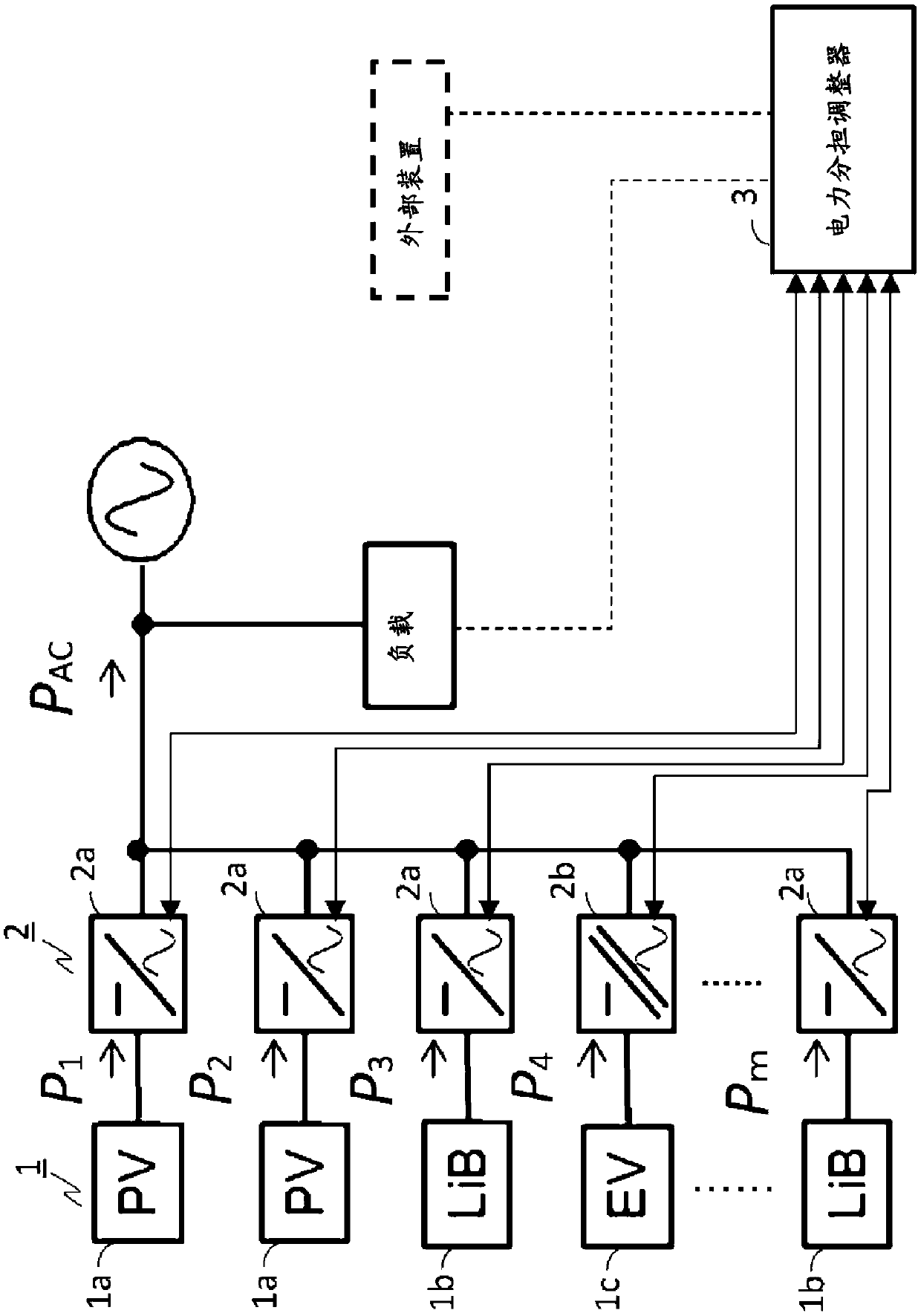
[0031] figure 1 It is a diagram showing an example of the configuration of the power conversion device according to Embodiment 1 of the present invention.
[0032] As shown in the figure, the power conversion device is equipped with a power sharing regulator 3. The power converter units 2 are connected in parallel at the output position. The power sharing regulator 3 adjusts each power converter unit (for example, Adjust the power value shared by each power converter unit). The power sharing regulator 3 has a function of acquiring power information corresponding to the rated efficiency point, maximum efficiency point, and allowable efficiency point of the power converter unit 2 used in the power conversion device. The requested power uses a value input to the power sharing regulator 3 from an external device, a control calculation result corresponding to an AC load or a flow power (see the dotted line connecting the load and the power sharing regulator 3 in the figure), or an...
Embodiment approach 2
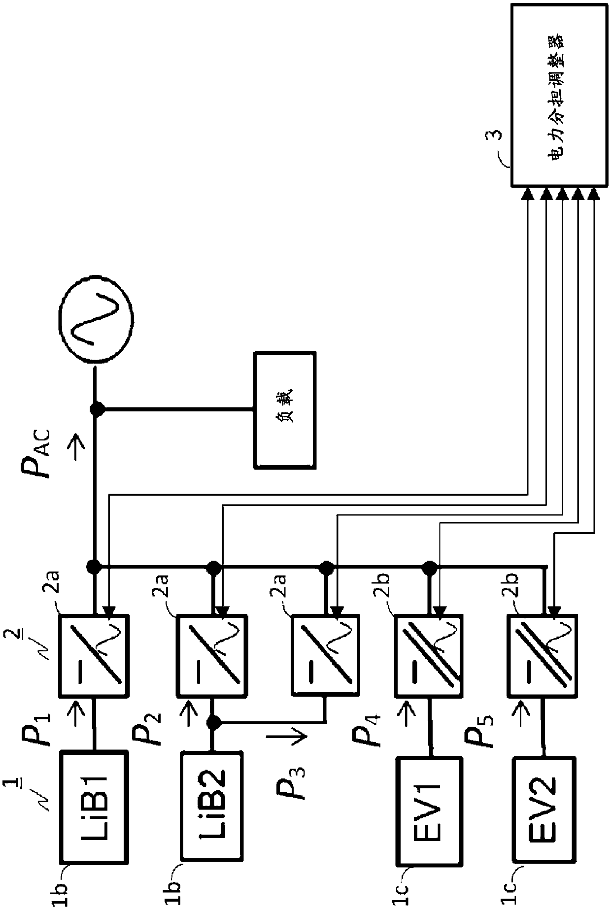
[0105] Figure 8 It is a diagram showing a configuration example of an operation mode selection flow according to Embodiment 2 of the present invention. In the power conversion device according to the second embodiment, compared with the first embodiment, a high-efficiency charging and discharging function that does not require the second power threshold and the third power threshold can be realized. Figure 8 A flowchart for realizing this function is shown. That is, by using a predetermined ratio to the first power threshold to determine the second power threshold and the third power threshold of the plurality of power converter units 2 operated by the power sharing regulator 3, it is possible to achieve a higher power ratio than that of the embodiment. 1 Simplified high-efficiency charge and discharge functions. For example, in Figure 8 In, set to P 2 =0.6P 1 , P 3 =0.4P 1 .
[0106] In Embodiment 2, as in Embodiment 1, one of the plurality of power converter units...
Embodiment approach 3
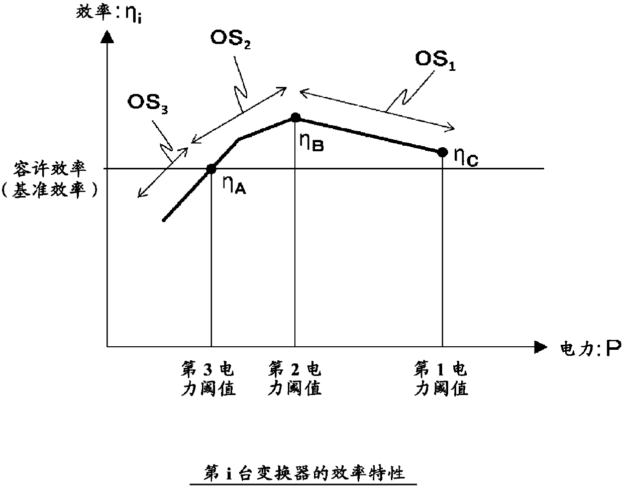
[0108] Figure 9It is a diagram showing a configuration example of an operation mode selection flow according to Embodiment 3 of the present invention. In addition to the configuration of Embodiment 1, the power conversion device according to Embodiment 3 is configured such that the power conversion efficiencies corresponding to the first power threshold to the third power threshold and the first power threshold and the second power threshold are used. The efficiency characteristic η obtained by linear approximation of the power conversion efficiency corresponding to the power threshold 1 and the efficiency characteristic η obtained by linearly approximating the power conversion efficiency corresponding to the second power threshold and the third power threshold 2 To realize the function of improving high-efficiency charging and discharging. Furthermore, for a linear approximation of the efficiency characteristic from the 3rd power threshold to zero, the efficiency character...
PUM
 Abstract
Description
Claims
Application Information
 - Generate Ideas
- Intellectual Property
- Life Sciences
- Materials
- Tech Scout
- Unparalleled Data Quality
- Higher Quality Content
- 60% Fewer Hallucinations
Browse by: Latest US Patents, China's latest patents, Technical Efficacy Thesaurus, Application Domain, Technology Topic, Popular Technical Reports.
© 2025 PatSnap. All rights reserved.Legal|Privacy policy|Modern Slavery Act Transparency Statement|Sitemap|About US| Contact US: help@patsnap.com