
Automatic stacking equipment

A palletizing and equipment technology, applied in the field of logistics transportation machinery and equipment, can solve the problems of easily damaged goods, low income and expenditure, and difficult promotion, and achieve stable and compact stacking, efficient palletizing action, and high input-income ratio Effect

Pending Publication Date: 2019-05-28
BEUMER MACHINERY MFG SHANGHAI
View PDF0 Cites 3 Cited by
  • Summary
  • Abstract
  • Description
  • Claims
  • Application Information

AI Technical Summary

Problems solved by technology

However, this design requires the investment of expensive industrial robots. For items with long rectangular cross-sections, when grabbing them, there must be two or more gripping points to prevent them from tipping over. The gripping strength is small and the package is easy to drop. In order to provide suitable gripping force for different weights of goods, the manipulator mechanism of robot palletizing is often complicated and heavy. There is a gap of at least the thickness of the claws, which makes the stamping shape not so stable, and an additional lateral pressing mechanism is required. At the same time, the process of robot palletizing must go through: grabbing by manipulators, attitude adjustment, moving, putting down, and empty hands Back to the position, for long strips with large mass inertia, the speed of the whole set of actions is relatively slow. If such a set of robotic automatic palletizers are used to stack long rectangular goods, the ratio of income to expenditure is not high, making it difficult to promote

Method used


Image

  • Automatic stacking equipment
  • Automatic stacking equipment
  • Automatic stacking equipment

Examples


Embodiment Construction

[0036] The present invention will be further described with reference to the drawings.

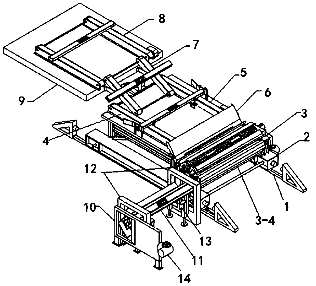
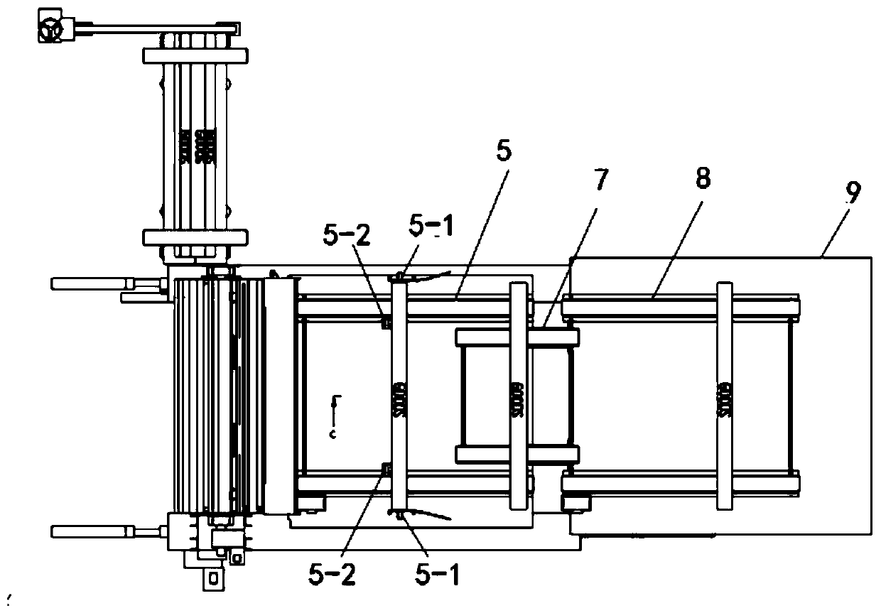
[0037] See Figure 1~8 , The present invention designs an automatic palletizing equipment, including a fixed belt conveyor, an inclined belt conveyor, a queuing belt conveyor composed of queuing feeder modules, a cargo posture adjustment module mainly composed of a rotating mechanism, a horizontal walking mechanism, Track and palletizing platform, track 1 is fixed on the ground, the track 1 is matched with a horizontal walking mechanism 2, a rotating mechanism 3 is fixed on the horizontal walking mechanism 2, and a frame 4 is installed in front of the rotating mechanism 3, and the frame 4 is also fixed On the horizontal traveling mechanism 2, a queuing belt conveyor 5 is fixed on the frame 4, and the front end of the queuing belt conveyor 5 and the rotating mechanism 3 are connected by a feeding chute 6, which is provided with There are open and close doors, which are controlled by air cylin...


PUM


Abstract

The invention relates to the technical field of logistics transportation mechanical equipment, in particular to automatic stacking equipment. A track is provided with a transverse walking mechanism ina cooperative manner. The transverse walking mechanism is fixedly provided with a rotating mechanism. A rack is arranged in front of the rotating mechanism. The rack is fixedly provided with a liningbelt conveyor. The front end of the lining belt conveyor is connected with the rotating mechanism through a piece supplying sliding groove. The rear end of the lining belt conveyor is connected witha fixing belt conveyor through an oblique belt conveyor. The fixing belt conveyor is fixedly installed on a platform. The platform is fixedly connected to a rack of the oblique belt conveyor through aconnecting rod. A stacking mechanism is arranged beside the transverse walking mechanism. By means of the automatic stacking equipment, complex and expensive industrial robots and manipulators are not needed, the structure is compact, maintaining is convenient through modular design, efficient full-automatic stacking action can be achieved only through several small ordinary air cylinders and electric pushing rods, the input return ratio is high, and the stability and compactness of stacking are guaranteed.

Description

Technical field [0001] The invention relates to the technical field of logistics transportation machinery and equipment, and specifically is an automatic palletizing equipment. Background technique [0002] For the palletizing of long rectangular items, the posture of the items is not easy to control during transportation and turning due to the shape biased toward the elongated shape. Therefore, the conventional belt conveyor and roller conveyor unit combined with the palletizer is not suitable. [0003] The most commonly used solution in the current industry is to use a palletizing robot, which is palletized one by one by picking, flipping, and placing one by one. However, this design requires the investment of expensive industrial robots. For items with long rectangular cross-sections, there must be two or more gripping points to prevent tipping. If the gripping force is too large, it is easy to damage the goods. In order to adapt to different weights of goods, the manipulator m...

Claims


Application Information

Patent Timeline
Patent Type & Authority Applications(China)
IPC IPC(8): B65G43/08B65G47/44B65G57/10B65G47/82B65G67/04B65B13/18
Inventor 谭恩龙黄旭明张小燕赵建立
Owner BEUMER MACHINERY MFG SHANGHAI
Learn More