Punching device suitable for floury soil and silt soil and using method
A punching device and technology for silt soil, applied in drilling equipment and methods, earthwork drilling, impact drilling and other directions, can solve the problems of unfavorable alluvial formation construction, low work efficiency, heavy equipment and other problems, and achieve the solution The problem of hole formation in alluvial soil layer, the effect of convenient production and reduction of engineering cost
- Summary
- Abstract
- Description
- Claims
- Application Information
AI Technical Summary
Problems solved by technology
Method used
Image

Examples
Embodiment 1
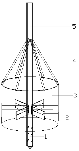
[0033] The punching device applicable to silty soil and silty soil of the present invention includes a standpipe, a cross knife, and a circular knife.
[0034] see now figure 1 , figure 1 It is a schematic structural diagram of a punching device according to an embodiment of the present invention. As shown in the figure, the vertical pipe is a steel pipe with a diameter of 32mm, the length of the steel pipe is 900mm, the bottom end of the vertical pipe is set as the punching head 1, the top of the punching head is provided with a steel pipe conical cover, and the side wall of the punching head is provided with an orifice The top of the vertical pipe is set as a steel pipe joint 5, and the steel pipe joint can be connected with a water pipe (not shown in the figure) to connect the water through the iron wire binding, and the water pipe is connected to the submersible pump, and the top of the vertical pipe can also be connected with a wooden pole of a certain length. (not show...
Embodiment 2
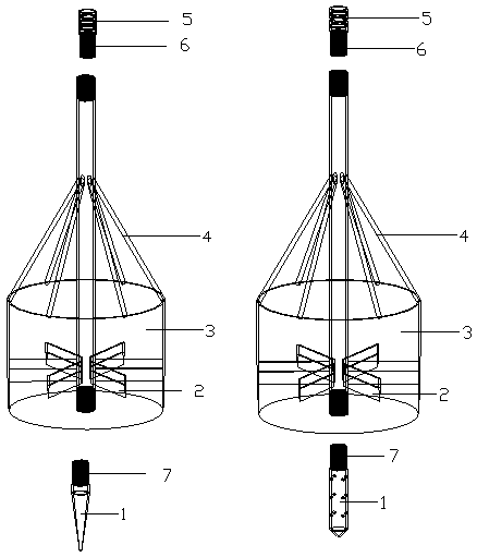
[0038] figure 2 It is another exploded schematic diagram of the structure of the punching device according to the embodiment of the present invention, illustrating that the steel pipe joint 5 becomes a steel pipe joint through the first screw connection unit 6; the punching head 1 becomes a replaceable punch through the second screw connection unit 7. hole head. In this embodiment, except that the diameter of the standpipe is a steel pipe of 50 mm, the cross knife is a steel plate with a width of 100 mm, the ring knife is a steel ring with a thickness of 6 mm, and the punching head is a detachable movable joint, which is convenient for replacement according to different soil layers and different apertures. Punching head, the punching head is a long tapered head with an aperture, the length of the tapered head is 150mm, except that the length of the threaded part is 50mm, all the other are the same as in embodiment 1.
Embodiment 3
[0040] The method for using the punching device applicable to silt and silt soil of the present invention comprises the following steps:
[0041] a. Connect the end of the steel pipe joint to the water pipe with iron wire, connect the end of the water pipe to the submersible pump, and place the submersible pump in the nearby reservoir;
[0042] b. Bind the steel pipe joint end firmly with the wooden pole with iron wire, and the length of the wooden pole is determined according to the punching depth;
[0043] c. Stand the vertical pipe upright, the punching head is perpendicular to the surface layer, turn on the submersible pump, and the water will flow through the outlet at the front end of the punching head to impact the soil layer;
[0044] d. The operator holds the wooden pole and slightly impacts the soil layer up and down. The circular knife cuts the soil layer and protects the surrounding soil layer to avoid excessive punching of the soil layer and other shapes of the so...
PUM
 Abstract
Description
Claims
Application Information
 - R&D Engineer
- R&D Manager
- IP Professional
- Industry Leading Data Capabilities
- Powerful AI technology
- Patent DNA Extraction
Browse by: Latest US Patents, China's latest patents, Technical Efficacy Thesaurus, Application Domain, Technology Topic.
© 2024 PatSnap. All rights reserved.Legal|Privacy policy|Modern Slavery Act Transparency Statement|Sitemap