Auxiliary stabilizing device for measuring equipment of small-sized surveying and mapping unmanned boat and auxiliary stabilizing method
A technology of measuring equipment and unmanned boats, which is applied in the direction of measuring devices, surveying and navigation, ships, etc., can solve problems such as measurement errors and affect measurement accuracy, and achieve the effects of avoiding delay errors, improving measurement accuracy, and improving relative stability
- Summary
- Abstract
- Description
- Claims
- Application Information
AI Technical Summary
Problems solved by technology
Method used
Image
Examples
Embodiment 1
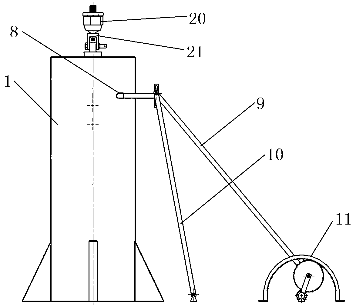
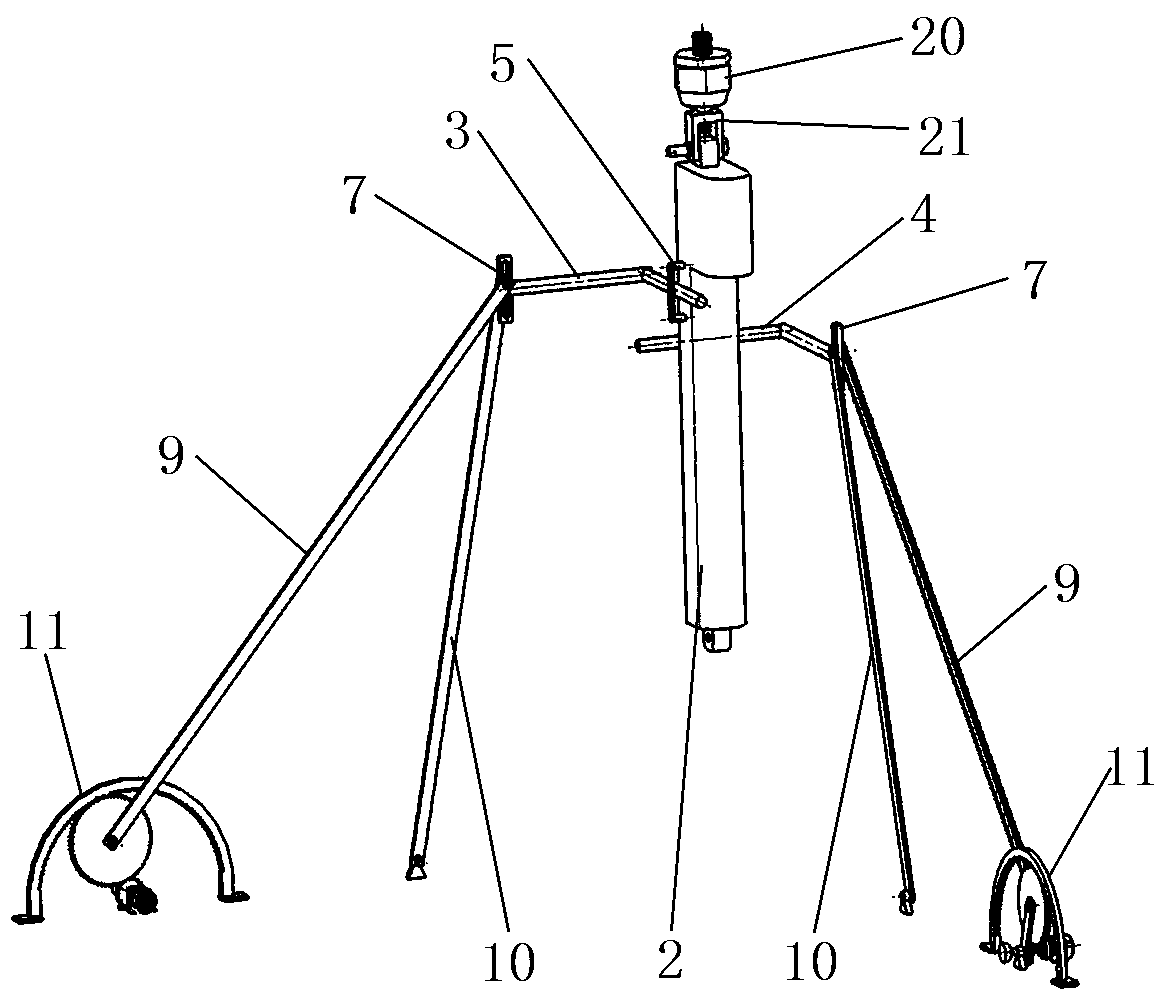
[0030] Such as Figure 1-3 The shown auxiliary stabilizing device for a small-scale surveying and mapping unmanned boat measuring equipment includes an electric push rod 2 connected in rotation with the unmanned boat, and the bottom end of the electric push rod 2 is fixedly connected with the measuring equipment; When the attitude of the body changes, by applying reverse attitude adjustment to the electric push rod 2, the adjustment of the swing amplitude of the measuring equipment fixedly connected with the electric push rod 2 is realized, and the influence of the measuring equipment by the swing of the hull is reduced, so that the measuring equipment Always point vertically to the bottom of the sea, improving the relative stability of the measuring equipment, thereby improving the measurement accuracy of the measuring equipment.
[0031] The electric push rod 2 is provided with a first L-shaped push rod 3 consistent with the hull direction and a second L-shaped push rod 4 pe...
Embodiment 2
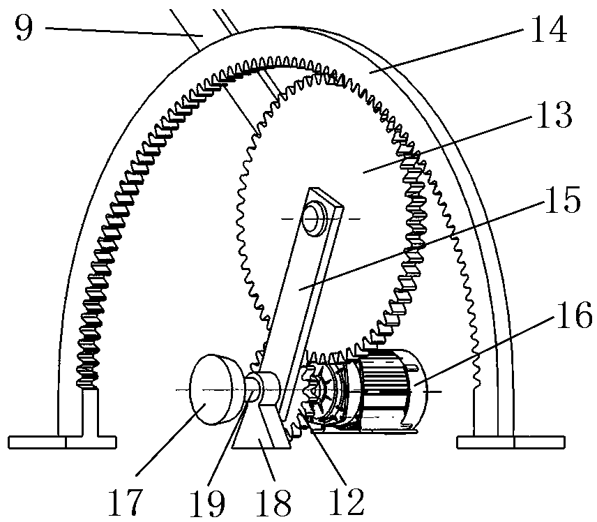
[0042] Such as Figure 4-6 As shown, when the crank rocker mechanism controls the first L-shaped push rod 3 to produce a linear motion along the linear linear bearing 8, the electric push rod 2 generates clockwise around the y-axis under the action of the first L-shaped push rod 3 direction, at this time, the stepper motor 16 controlling the second L-shaped push rod 4 is not started, the second L-shaped push rod 4 does not move, and is in a relatively static state. When rotating in the clockwise direction, the second Π-shaped stopper 6 fixed on the electric push rod 2 and the electric push rod 2 produce the same movement, because the second L-shaped push rod 4 and the second Π-shaped stopper 6 The sliding fit between them makes the second Π-shaped stopper 6 relatively slide relative to the stationary second L-shaped push rod 4, and in this process, the movement of the second L-shaped push rod 4 is not caused, that is, Realize the linear movement of the first L-shaped push rod...
Embodiment 3
[0045] Such as Figure 7 and Figure 8 As shown, the method for assisting stabilization by utilizing the auxiliary stabilization device of the above-mentioned small surveying and mapping unmanned ship surveying equipment includes the following steps:
[0046] S01: Making of the mapping table: in the static state of the hull, start the stepper motor 16 that controls the movement of the first L-shaped push rod 3, and use the first L-shaped push rod 3 to compare the front and rear of the electric push rod 2 relative to the hull The active force in the direction realizes the front and rear deflection of the electric push rod 2 relative to the hull, and records the rotation angle of the stepper motor 16 when the electric push rod 2 is deflected relative to the front and rear deflection angle of the boat body; the second L-shaped push rod 4 is started to control the movement The stepper motor 16 uses the force of the second L-shaped push rod 4 on the left and right direction of the...
PUM
 Abstract
Description
Claims
Application Information
 - R&D
- Intellectual Property
- Life Sciences
- Materials
- Tech Scout
- Unparalleled Data Quality
- Higher Quality Content
- 60% Fewer Hallucinations
Browse by: Latest US Patents, China's latest patents, Technical Efficacy Thesaurus, Application Domain, Technology Topic, Popular Technical Reports.
© 2025 PatSnap. All rights reserved.Legal|Privacy policy|Modern Slavery Act Transparency Statement|Sitemap|About US| Contact US: help@patsnap.com


