
Method for measuring vertical dynamic disturbance of high-speed railway bridge based on unmanned aerial vehicle

A measurement method and unmanned aerial vehicle technology, which is applied in the testing of machines/structural components, measuring devices, elastic testing, etc., can solve the requirements of high environmental requirements, affecting the stability of the camera attitude, and difficulty in meeting sub-millimeter level measurement accuracy requirements and other problems, to achieve high-precision measurement, simple and efficient measurement process

Active Publication Date: 2019-05-28
SUN YAT SEN UNIV +1
View PDF6 Cites 5 Cited by
  • Summary
  • Abstract
  • Description
  • Claims
  • Application Information

AI Technical Summary

Problems solved by technology

[0004] In addition, the camera has high requirements on the environment when imaging, because the measurement process is easily affected by the environment, so that the final measurement accuracy cannot meet the requirements
For example, when the camera is installed near the road, the road vibration caused by passing vehicles will directly affect the attitude stability of the camera, and it is difficult to meet the measurement accuracy requirements of the submillimeter level

Method used


Image

  • Method for measuring vertical dynamic disturbance of high-speed railway bridge based on unmanned aerial vehicle
  • Method for measuring vertical dynamic disturbance of high-speed railway bridge based on unmanned aerial vehicle
  • Method for measuring vertical dynamic disturbance of high-speed railway bridge based on unmanned aerial vehicle

Examples


Embodiment Construction

[0049] Embodiments of the present invention will be further described in detail below in conjunction with the accompanying drawings.

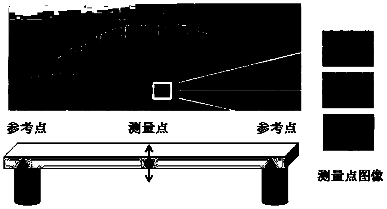
[0050] Such as figure 1 As shown, the disturbance refers to the displacement of the centroid of the cross section perpendicular to the axial direction of the beam after the beam is bent and deformed, the position of the cross section in the beam will change. So the disturbance is the change in position of the cross section in the beam relative to the fixed end points of the beam.

[0051] For the high-speed rail bridge (simply supported beam type), it can be considered that the two ends of the bridge where the two pier support points at the left and right ends of the high-speed rail bridge are located are static and unchanged, and the mid-span position of the high-speed rail bridge is in the vertical direction relative to the two ends. The position change is the vertical disturbance degree of the high-speed rail bridge.

[0052] When using a ...


PUM


Abstract

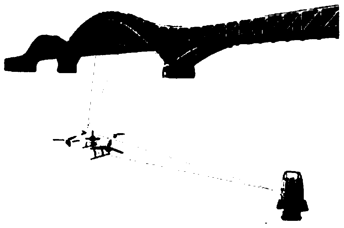
The invention relates to a method for measuring the vertical dynamic disturbance of a high-speed railway bridge based on an unmanned aerial vehicle, which is characterized in that measuring points arearranged on a high-speed railway bridge to be measured. A camera is installed on the unmanned aerial vehicle, and markers are arranged on the unmanned aerial vehicle. A total station instrument is arranged on the ground. The method comprises the following steps: controlling the unmanned aerial vehicle to fly to a set position on a horizontal plane of the measuring points and a vertical line vertical to the measuring points, shooting and imaging the measuring points on the high-speed railway bridge to be measured by using the camera on the unmanned aerial vehicle according to a set time interval at the set position, and synchronously measuring the position coordinates of markers on the unmanned aerial vehicle according to the same set time interval as the camera on the unmanned aerial vehicle by using the total station instrument; correcting the image coordinates of the measuring points by using the data output by the total station instrument and the inertial navigation of the unmannedaerial vehicle, and obtaining the vertical dynamic disturbance of the high-speed railway bridge based on the corrected image coordinates of the measuring points. The method is not influenced by environmental vibration, can achieve flexible and easy-to-operate high-precision measurement of the dynamic disturbance of the high-speed railway bridge, and has simple and efficient measurement process.

Description

technical field [0001] The invention relates to the technical field of visual measurement of bridge dynamic displacement, in particular to a method for measuring the vertical disturbance of a high-speed rail bridge by using an unmanned aerial vehicle. Background technique [0002] The dynamic displacement measurement of the high-speed rail bridge based on visual measurement technology needs to set up a camera equipped with a telephoto lens near the bridge to be tested, and use the camera to image the part of the bridge to be tested, record the position of the part to be tested on the image at different times, and then according to the bridge to be tested The position change of the measured part on the image is used to calculate the actual position change of the bridge to be measured, so as to obtain the dynamic displacement of the bridge part. The part to be tested can be a natural surface on the bridge, or a specially made optical mark can be pasted or fixed. [0003] The ...

Claims


Application Information

Patent Timeline
Patent Type & Authority Applications(China)
IPC IPC(8): G01M5/00
Inventor 张小虎林彬甘叔玮叶雪辀杨夏王卫东黄天立
Owner SUN YAT SEN UNIV
Learn More