MTD radar defuzzification and speed measurement method

A defuzzification and radar technology, applied in the field of radar, can solve the problems of unresolved speed measurement, less pulse number, and unstable system

Active Publication Date: 2019-05-28
XIDIAN UNIV
View PDF3 Cites 15 Cited by
  • Summary
  • Abstract
  • Description
  • Claims
  • Application Information

AI Technical Summary

Problems solved by technology

[0004] Existing methods need to first judge whether the echo signal of the target is in the noise area or the clutter area, and then switch to the discrete Fourier transform (English full name: Discrete Fourier Transform, English abbreviation: DFT) channel or finite-length unit impulse according to the judgment result. The stimulus response (English full name: Finite Impulse Response, English abbreviation: FIR) channel detects the moving target on the echo signal of the target. steady
In addition, the existing methods need to perform moving target detection on the DFT channel or FIR channel to detect the target sig

Method used


Image

  • MTD radar defuzzification and speed measurement method
  • MTD radar defuzzification and speed measurement method
  • MTD radar defuzzification and speed measurement method

Examples


Embodiment Construction

[0023] The following will clearly and completely describe the technical solutions in the embodiments of the present invention with reference to the accompanying drawings in the embodiments of the present invention. Obviously, the described embodiments are only some, not all, embodiments of the present invention. Based on the embodiments of the present invention, all other embodiments obtained by persons of ordinary skill in the art without making creative efforts belong to the protection scope of the present invention.

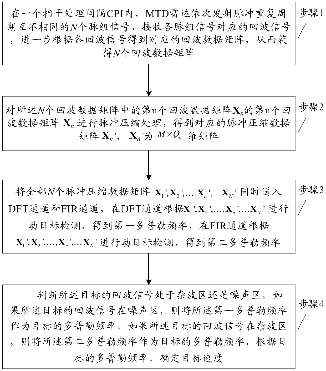
[0024] figure 1 A schematic flowchart of an MTD radar defuzzification speed measurement method is provided for an embodiment of the present invention.

[0025] see figure 1 , a kind of MTD radar defuzzification velocity measuring method provided by the embodiment of the present invention, comprises the following steps:

[0026] Step 1. Within a coherent processing interval CPI, the MTD radar sequentially transmits N pulse group signals with different pulse r...


PUM


Abstract

The invention belongs to the technical field of radars, and discloses an MTD radar defuzzification and speed measurement method. The method comprises the following steps that in a CPI, pulse group signals with different pulse repetition periods are sequentially transmitted by an MTD radar, echo signals corresponding to the pulse group signals are received, an echo data matrix corresponding to each pulse group signal is obtained, moving target detection is carried out on the echo data matrix compressed by all pulses in a DFT channel and an FIR channel respectively, a first Doppler frequency and a second Doppler frequency are obtained respectively, whether echo signals of a target are in a clutter area or a noise area is judged, the Doppler frequencies obtained by one of the channels are selected as the target Doppler frequency according to a judgment result, and the target speed is further determined. The method can improve the robustness of the system and the resource utilization rateof the radar, so that the signal-to-noise ratio of the target signal is improved, and the detection probability of the target signal and the success rate of speed ambiguity resolution are improved.

Description

technical field [0001] The present invention relates to the field of radar technology, in particular to a moving target detection (English full name: Moving Target Detection, English abbreviation: MTD) radar defuzzification velocity measurement method. Background technique [0002] MTD radar usually works with low pulse repetition frequency (English full name: Pulse Repetition Frequency, English abbreviation: PRF). When the moving speed of the target exceeds the maximum unambiguous speed of the radar, it will cause the moving speed of the target to overlap in the Doppler domain. , which is called speed ambiguity, so to obtain the moving speed of the target, it is necessary to solve the speed ambiguity. [0003] Most of the traditional speed fuzzy resolution algorithms use the Chinese Remainder Theorem (English full name: Chinese Remainder Theorem, English abbreviation: CRT) or similar algorithms to achieve fuzzy resolution on the basis of the variable pulse repetition period...

Claims


Application Information

Patent Timeline
IPC IPC(8): G01S7/292G01S13/58
Inventor 赵永波剡熠琛何学辉刘宏伟苏洪涛
Owner XIDIAN UNIV
Why Eureka
Try Eureka