
Infrasound sensor and realizing method thereof

A sensor, acceleration sensor technology, used in the measurement of ultrasonic/sonic/infrasonic waves, instruments, seismic signal receivers, etc., can solve problems such as interference, high cost, and complex use

Pending Publication Date: 2019-05-28
KUNMING UNIV OF SCI & TECH
View PDF0 Cites 0 Cited by
  • Summary
  • Abstract
  • Description
  • Claims
  • Application Information

AI Technical Summary

Problems solved by technology

[0003] The technical problem to be solved by the present invention is: the present invention provides an infrasound sensor and its implementation method, which are used to solve the problems of high cost, complicated use and more interference in the existing seismic monitoring methods

Method used


Image

  • Infrasound sensor and realizing method thereof
  • Infrasound sensor and realizing method thereof
  • Infrasound sensor and realizing method thereof

Examples


Embodiment 1

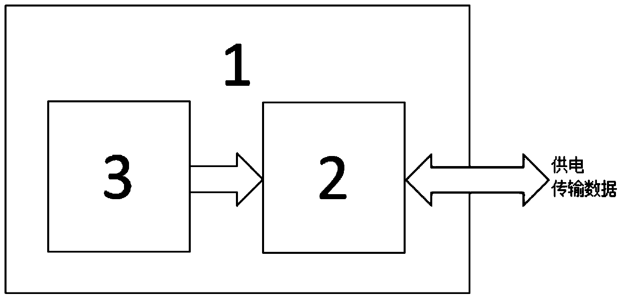
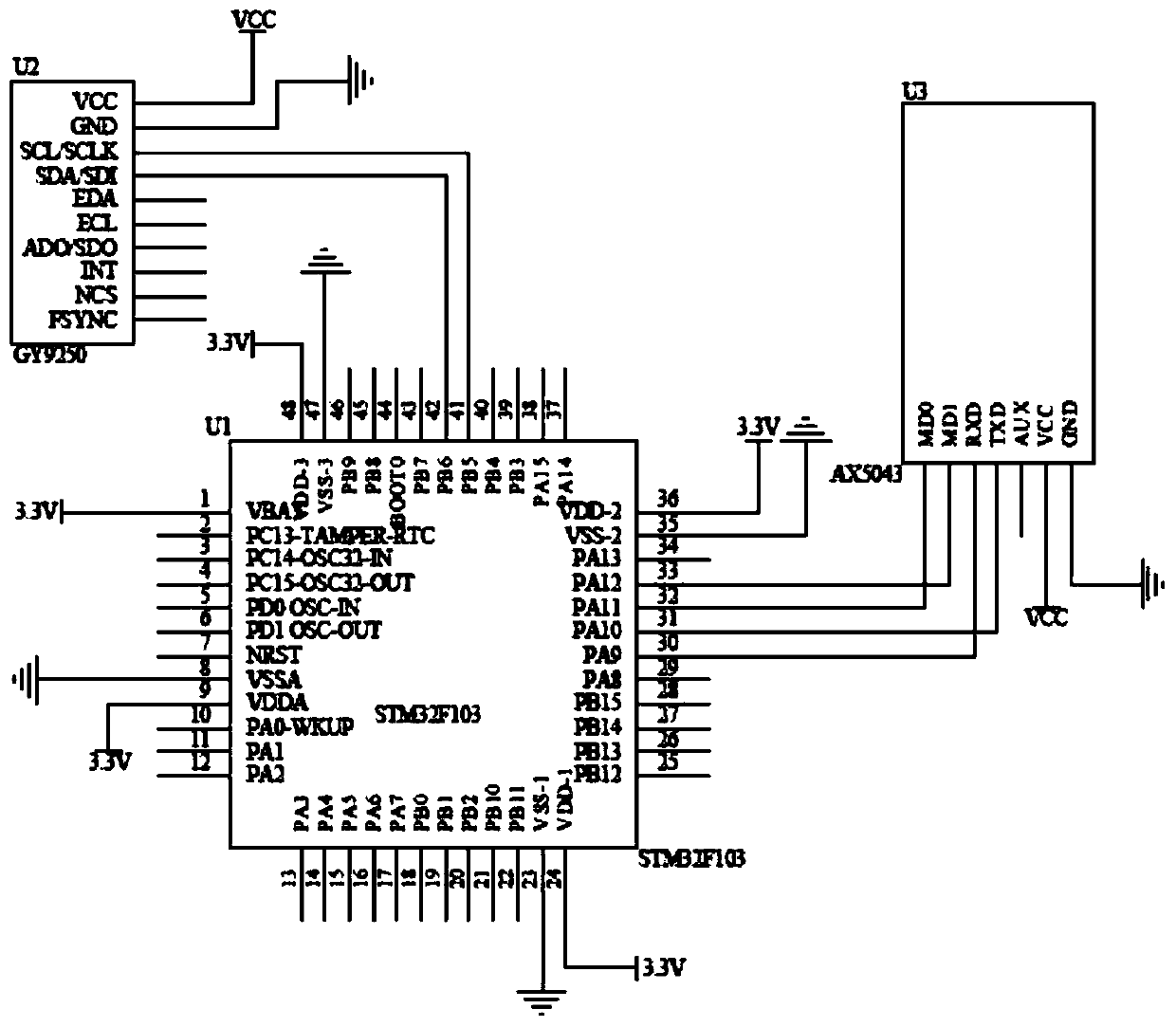
[0058] Embodiment 1: as Figure 1-2 As shown, an infrasound sensor includes a plastic shell 1, a single-chip microcomputer 2, and an acceleration sensor 3; wherein the acceleration sensor 3 is connected to the single-chip microcomputer 2, and the acceleration sensor 3 and the single-chip microcomputer 2 are hermetically packaged through the plastic shell 1 and buried in the ground. The plastic shell 1 Adopt airtight and waterproof strong plastic shell.

[0059] Further, the acceleration sensor 3 adopts the MPU-9250 nine-axis sensor.

[0060] Further, the acceleration sensor 3 is connected to the single-chip microcomputer 2 through i2c communication, and the single-chip microcomputer 2 adopts STM32F103; wherein, the SCL port of the MPU-9250 is connected to the PB5 port of the single-chip microcomputer 2, the SDA port is connected to the PB6 port of the single-chip microcomputer 2, and the VCC port is connected to the power supply VCC , the GND port is grounded.

[0061]The MP...

Embodiment 2

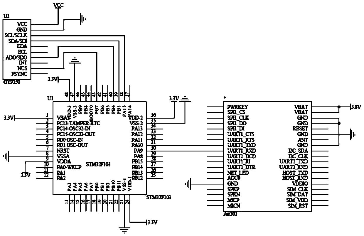
[0084] Embodiment 2: as figure 1 , image 3 As shown, a kind of infrasound sensor and its implementation method, this embodiment is the same as embodiment 1, and wherein difference is:

[0085] Further, the acceleration sensor 3 is connected to the single-chip microcomputer 2 through SPI communication, and the single-chip microcomputer 2 adopts STM32F103; wherein, the SCLK port of the MPU-9250 is connected to the PA15 port of the single-chip microcomputer 2, the SDI port is connected to the PB3 port of the single-chip microcomputer 2, and the SDO port is connected to the single-chip microcomputer 2 The PB4 port of the MCU, the NCS port is connected to the PB7 port of the microcontroller 2, the VCC port is connected to the power supply VCC, and the GND port is grounded.

[0086] The MPU-9250 nine-axis sensor (U2) communicates with the MCU 2 (U1) through two data lines, a chip selection signal line and a clock line. When there are two MPU-9250 nine-axis sensors, you only need ...

Embodiment 3

[0088] Embodiment 3: as Figure 1-3 As shown, a kind of infrasound sensor and its implementation method, this embodiment is the same as embodiment 1, and wherein difference is:


PUM


Abstract

The invention relates to an infrasound sensor and a realizing method thereof, and belongs to the technical field of earthquake monitoring. The infrasound sensor comprises a plastic shell, a circuit board including a single chip microcomputer and an acceleration sensor and an outgoing line; the acceleration sensor on the circuit board is connected with the single chip microcomputer, and the circuitboard is packaged with airtightness through the plastic shell with sealing performance and waterproofness. The realizing method includes the steps that a mode is set; a device is installed; an infrasound signal is read; interference removal is conducted on the infrasound signal; the amplitude frequency of the infrasound signal is converted; data is sent; circulating monitoring is conducted. The infrasound sensor is packaged with airtightness and put under the ground or at a deepwater position to detect underground earthquake precursor infrasounds. The infrasound sensor has the advantages of being low in cost, convenient to use, simple, reliable, small in size, easy to carry and install and the like.

Description

technical field [0001] The invention relates to an infrasound sensor and a realization method thereof, belonging to the technical field of earthquake monitoring. Background technique [0002] Major earthquakes have caused great disasters to human beings. In the 21st century, major earthquakes are becoming more and more frequent, and the prediction of major earthquakes is very urgent. With the deepening of human research on earthquakes, a large amount of research data shows that seismic infrasound waves will be emitted during the process of earthquake breeding. If the characteristics of seismic infrasonic waves can be analyzed and monitored, it will be of great help to predict the time, epicentre and magnitude of the earthquake in advance, which will also greatly reduce the harm of earthquakes, so we will detect the precursors of major earthquakes Infrasound offers a solution. Many scholars have conducted research and discovered the characteristics of infrasonic waves that ...

Claims


Application Information

Patent Timeline
IPC IPC(8): G01V1/18G01P15/125G01H11/06
Inventor 邵建龙薛春邵馨叶金建辉刘羽升王奕文李重
Owner KUNMING UNIV OF SCI & TECH
Learn More