A High Gain Voltage Type Quasi-Y Source DC-DC Converter

A DC converter, voltage-type technology, applied in the direction of converting DC power input to DC power output, adjusting electrical variables, instruments, etc., can solve problems such as limited boosting capacity, increased circuit cost, and complex control of the converter, and achieve voltage The effect of high gain, small start-up inrush current, and continuous input current

Active Publication Date: 2020-11-17
SHANDONG UNIV OF SCI & TECH
View PDF5 Cites 0 Cited by
  • Summary
  • Abstract
  • Description
  • Claims
  • Application Information

AI Technical Summary

Problems solved by technology

The voltage-type / current-type impedance source DC converter based on the idea of ​​traditional impedance source converter can overcome the above-mentioned defects of poor reliability of the circuit, but its boosting capability is limited. To further increase the voltage gain, it is necessary to stage the impedance source network This not only greatly increases the cost of the circuit, but also makes the control of the converter relatively complicated.

Method used


Image

  • A High Gain Voltage Type Quasi-Y Source DC-DC Converter
  • A High Gain Voltage Type Quasi-Y Source DC-DC Converter
  • A High Gain Voltage Type Quasi-Y Source DC-DC Converter

Examples


Embodiment

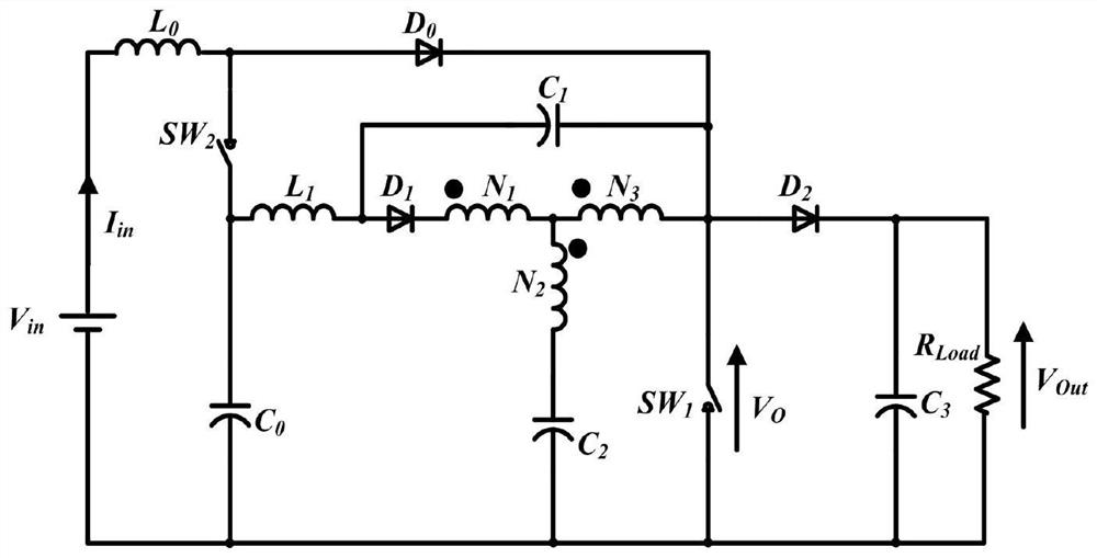
[0036] When SW 1 closed, SW 2 When disconnected, the circuit of the present invention is in a straight-through state, and the circuit connection situation is: V in Positive through L 0 Connect back to V in Negative pole, L 0 with V in The nodes between the negative poles pass through the third end of the three-winding coupled inductor in turn, and the second end of the three-winding coupled inductor passes through C 2 Connect back to V in Negative pole, L 0 with V in The nodes between the negative poles also pass through C in turn 1 , L 1 and C 0 Connect back to V in negative electrode.

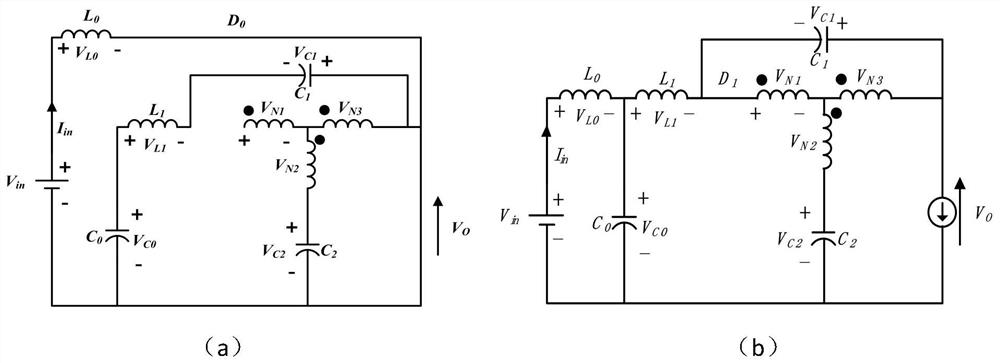
[0037] like image 3 (a) The circuit shown in (a) works in a straight-through state, and the diode D 0 conduction, the diode D 1 and D 2 is reverse biased and turned off. Applying Kirchhoff's Voltage Law (KVL) in this mode, the voltage equation in the shoot-through state is:

[0038] -V in +V L0 =0 (1)

[0039] -V C0 +V L1 -V C1 =0 (2)

[0040] V C2 +V N2 -V N3 =0 ...


PUM


Abstract

The invention discloses a high-gain voltage type quasi-Y source direct current-direct current converter. A Y source network and a Boost impedance network are combined, the voltage gain of a circuit isflexibly determined through a three-winding transformer in the Y source network, and higher boosting can be achieved under the same duty ratio. Therefore, the problem that the traditional Boost converter can only obtain higher output voltage by increasing the duty ratio, however, the current peak values of the output diode and a switching tube are increased, the conduction loss and the capacitance impact are increased, the conversion efficiency of the circuit is low, and the service life of the circuit is short is solved, so that the converter has the advantages of high conversion efficiencyand high voltage gain, and the circuit structure is simple and reliable.

Description

technical field [0001] The invention relates to the technical field of DC-DC converters, in particular to a high-gain voltage-type quasi-Y source DC-DC converter. Background technique [0002] With the development of human society, industrial production has led to more and more energy consumption around the world, and the rapid reduction of non-renewable energy reserves represented by fossil fuels has led to increasingly serious supply shortages. Therefore, renewable energy has become a research hotspot for many scholars due to its clean and sustainable development characteristics. For new energy generation methods, whether it is photovoltaic power generation or fuel cell power generation, the output voltage fluctuates greatly, so it is necessary to use high-gain The DC-DC conversion circuit of the ratio ensures that the output voltage is a higher stable DC voltage. At present, the widely used DC-DC converters include direct circuits and transformer-isolated circuits, which...

Claims


Application Information

Patent Timeline
Patent Type & Authority Patents(China)
IPC IPC(8): H02M3/156
Inventor 房绪鹏丁晓康张炜烁
Owner SHANDONG UNIV OF SCI & TECH
Why Eureka
Try Eureka