Non-isolated bidirectional DC/DC converter with high step-up ratio

A high boost ratio, converter technology, used in output power conversion devices, DC power input to DC power output, instruments and other directions, can solve the overall efficiency limit, reduce converter efficiency, low-voltage side current problems such as large , to achieve the effect of clear circuit structure, easy expansion, and high boost ratio

Inactive Publication Date: 2019-02-05
BEIJING DEYI XINNENG ELECTRICAL CO LTD
View PDF7 Cites 7 Cited by
  • Summary
  • Abstract
  • Description
  • Claims
  • Application Information

AI Technical Summary

Problems solved by technology

[0003] DC microgrid bus voltage is generally 100 to 400V, while the output voltage of photovoltaics and fuel cells is generally between 25 and 45V. If a traditional non-isolated DC / DC converter is used to connect photovoltaics and fuel cells to the bus voltage is In a 380V DC microgrid, the duty cycle of the switching tube will be close to 1. At this time, because the boost ratio is too high, the current at the low-end voltage is very large, and the actual efficiency of the system will be very low.
In addition, although multi-stage converters can be connected in series to achieve a very high boost ratio, but the low-voltage side current is large, and the total efficiency of the system is the product of the efficiencies of the converters at all levels, so the overall efficiency will be limited.
If an isolated DC / DC converter is used, the number of turns of the secondary winding of the transformer to the primary winding is relatively high, which will cause poor coupling of the primary and secondary windings and cause a large leakage inductance
A large leakage inductance will cause a high voltage spike on the switch tube, which will seriously reduce the efficiency of the converter

Method used


Image

  • Non-isolated bidirectional DC/DC converter with high step-up ratio
  • Non-isolated bidirectional DC/DC converter with high step-up ratio
  • Non-isolated bidirectional DC/DC converter with high step-up ratio

Examples


Embodiment Construction

[0019] The present invention will be further described below with reference to the accompanying drawings and examples, and the embodiments of the present invention include but not limited to the following examples.

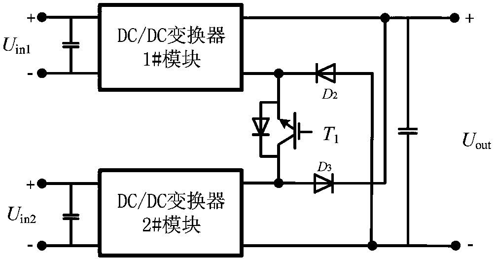
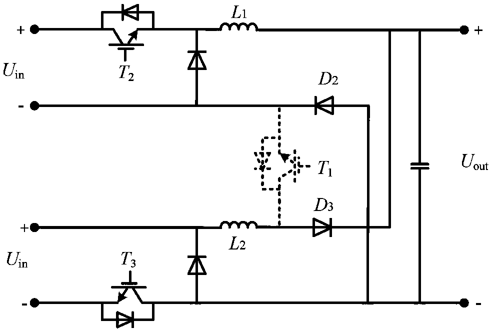
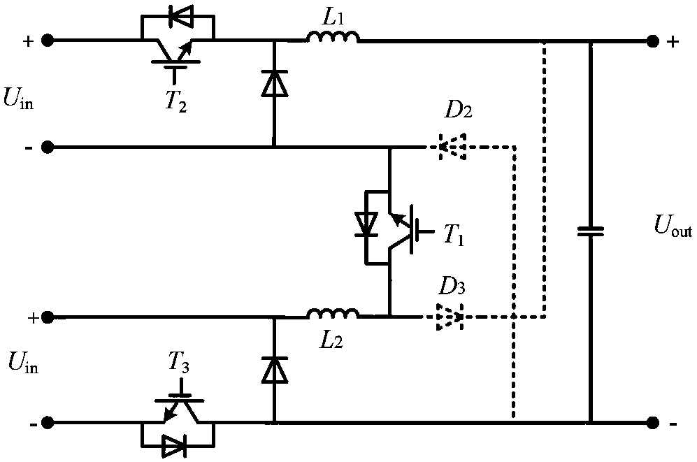
[0020] A non-isolated bidirectional DC / DC converter with a high step-up ratio. The converter has a multi-module input parallel connection and output series topology. The inductor current of each module is the same, and the actual processing power of each stage is also the same. The total output voltage of the converter is the sum of the output voltage and the input voltage of all modules, and the overall boosted voltage is distributed to each module, so the boost ratio that needs to be achieved by a single module is reduced. This structure effectively improves the converter overall efficiency. When the gap between the output voltage and the input voltage is large, the output voltage to be borne by each module becomes higher, but the input parallel structure of the...


PUM


Abstract

The invention discloses a non-isolated bidirectional DC/DC converter with high step-up ratio, which can realize wide range and high step-up ratio adjustment. A converter system consists of several standard modules, and the standard modules uses BUCK-BOOST circuits as basic topology. The standard modules adjust the switching tube duty cycle through the respective closed-loop control loops to achieve their respective voltage rises. The system connects the outputs of multiple modules in series to achieve the rise of the total output voltage of the system. The total output voltage is the sum of the input voltage of the lower voltage and the output voltage of each standard module. The whole system distributes the total output voltage to each standard module by connecting the input terminals inparallel and the output terminals in series. The boosting comparison system of each level module reduces the total boost ratio, therefore, each stage module has a wide range of duty cycle adjustment,and the purpose of adjusting the overall duty cycle of the converter is wide. At the same time, the overall converter system makes the overall efficiency of the converter high by adopting parallel connection of the output terminals.

Description

technical field [0001] The invention relates to the technical field of DC / DC converters, in particular to a non-isolated bidirectional DC / DC converter with a high boost ratio, which can still operate efficiently and stably when the difference between input and output voltages is large. Background technique [0002] With the increasing tension of environmental and resource issues, people pay more and more attention to the development and utilization of new energy, and microgrid, as an effective form of organizing new energy generation and energy storage, has been extensively and deeply studied since it was proposed. Photovoltaic and energy storage systems are generally connected to the microgrid for control and application. The output voltage of the photovoltaic and energy storage system in the microgrid is generally low, while the DC bus voltage is relatively high. If the photovoltaic and energy storage system is connected to the DC microgrid, a DC / DC converter with a relati...

Claims


Application Information

Patent Timeline
Patent Type & Authority Applications(China)
IPC IPC(8): H02M3/156H02M1/14
CPCH02M1/14H02M3/156
Inventor 吴学智郅欢程盛童亦斌张维戈姜久春
Owner BEIJING DEYI XINNENG ELECTRICAL CO LTD
Why Eureka
Try Eureka