A portable drug injector

A portable and pharmaceutical technology, which is applied in the field of medical devices, can solve the problems of unfavorable drug absorption and utilization, increase the burden on the heart, shorten the infusion time, etc., and achieve the effect of avoiding uneven blood drug concentration, being convenient to move and carry, and improving the efficacy of drugs

Active Publication Date: 2021-02-19
合肥九州龙腾科技成果转化有限公司
View PDF10 Cites 0 Cited by
  • Summary
  • Abstract
  • Description
  • Claims
  • Application Information

AI Technical Summary

Problems solved by technology

This infusion mode will bring many problems in actual use: the flow rate is adjusted manually, and the flow control accuracy is not enough; the infusion bottle needs to be held high by others when the patient walks or goes to the toilet, which is inconvenient to move and the height of the infusion bottle is not high enough. Make the blood flow back; patients or nurses need to be guarded for a long time, if the infusion is not found in time, it may cause accidents; the liquid medicine is in contact with the air, and the ambient air may be polluted when the air is unclean
In addition to the above direct problems, sometimes the infusion time is shortened by reducing the amount of solution, speeding up the infusion speed, etc., which not only increases the burden on the heart, but also affects the therapeutic effect: intramuscular injection and subcutaneous injection in a relatively short period of time. The biggest disadvantage of injecting into muscle or subcutaneous is that the blood drug concentration varies greatly within an injection cycle, which is not conducive to the effective absorption and utilization of drugs, because most drugs have a better concentration range in the human body, and when the drug concentration is too high Has toxic side effects, if it is too low, it will have no therapeutic effect

Method used


Image

  • A portable drug injector
  • A portable drug injector
  • A portable drug injector

Examples


Embodiment Construction

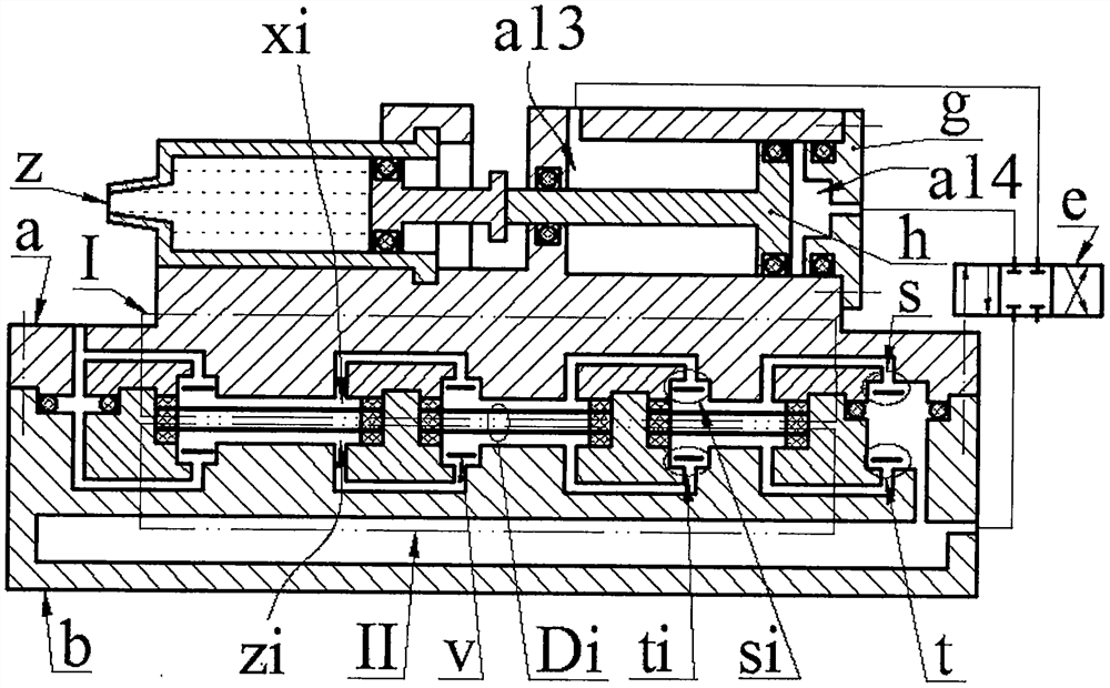
[0017]The top of the main body a is equipped with a syringe z, a cylinder cavity a11 and a baffle a9 with a sliding groove a10, the center line of the cylinder cavity a11 is in the horizontal plane; the cylinder cavity a11 is sleeved with the main piston h, and the cylinder cavity a11 is on the side The end of the wall is equipped with a cylinder head g; the main piston h separates the cylinder cavity a11 into a left cavity a13 and a right cavity a14; the syringe z is composed of a cartridge z1 and a secondary piston z2, and the secondary piston z2 is placed in the cartridge z1 and is combined with the drug The cylinder z1 constitutes the medicine cavity z3, the ear plate z4 at one end of the medicine cylinder z1 is placed in the sliding groove a10 of the baffle a9, and the other end is equipped with an infusion tube with a needle; the push rod of the main piston h passes through the left wall a12 of the cylinder cavity The through hole extends and bears against the push rod of the ...


PUM


Abstract

The invention relates to a portable drug injector, which belongs to the field of medical equipment. The top of the main body is equipped with a syringe and a cylinder chamber. The main piston divides the cylinder chamber into left and right chambers. The push rod of the main piston protrudes through the left wall of the cylinder chamber and leans against the push rod of the auxiliary piston; the main body is installed on the box. The left and right bosses of the main body are respectively placed in the left and right sinking cavities of the box, and the upper inlet and outlet holes of the main body are respectively connected with the upper inlet and outlet holes of the box; the body platform of the main body crimps the driver to the body cavity of the box through a sealing ring The upper and lower compression chambers are formed inside and the diameter of the upper and lower compression chambers gradually decreases from left to right. The upper and lower compression chambers are connected in series and then in parallel; the transducer is composed of two piezoelectric vibrators and a gasket in the middle, and the piezoelectric vibrator is composed of a It is bonded with the piezoelectric sheet; during work, the deformation directions of the two piezoelectric vibrators in the same transducer are the same, and the deformation directions of the piezoelectric vibrators in the left and right adjacent drivers are opposite; The valve is connected, and the reversing valve is connected with the gas storage chamber through the gas delivery pipe.

Description

Technical field[0001]The invention belongs to the field of medical equipment, and particularly relates to a portable medicine bolus injector.Background technique[0002]Injection administration mainly includes intravenous injection, intramuscular injection and subcutaneous injection. Intravenous injection is also called infusion administration. The existing infusion devices are mostly composed of infusion bottles, infusion tubes and infusion frames. The infusion bottles are hung on the infusion stand, flow by the weight of the medicinal solution, and are injected into human blood vessels through the infusion tube. This infusion mode will bring many problems in actual use: manual method is used to adjust the flow rate, the flow control accuracy is not enough; the patient needs to hold the infusion bottle high when the patient is walking, going to the toilet, etc., and the movement is not convenient and the infusion bottle is not high enough. Make the blood flow back; patients or nurses...

Claims


Application Information

Patent Timeline
Patent Type & Authority Patents(China)
IPC IPC(8): A61M5/155A61M5/168
Inventor 李建平刘晨欣丁璐瑶徐晨阳张忠华林仕杰曾平
Owner 合肥九州龙腾科技成果转化有限公司
Why Eureka
Try Eureka