A drug delivery device driven by gas step-by-step compression

A technology of compression drive and drug delivery device, applied in the field of medical devices, can solve the problems of unfavorable drug absorption and utilization, increase the burden on the heart, and have no therapeutic effect, avoid uneven blood drug concentration, facilitate movement and portability, and prolong injection. effect of time

Active Publication Date: 2021-04-30
ZHEJIANG NORMAL UNIVERSITY
View PDF4 Cites 0 Cited by
  • Summary
  • Abstract
  • Description
  • Claims
  • Application Information

AI Technical Summary

Problems solved by technology

This infusion mode will bring many problems in actual use: the flow rate is adjusted manually, and the flow control accuracy is not enough; the infusion bottle needs to be held high by others when the patient walks or goes to the toilet, which is inconvenient to move and the height of the infusion bottle is not high enough. Make the blood flow back; patients or nurses need to be guarded for a long time, if the infusion is not found in time, it may cause accidents; the liquid medicine is in contact with the air, and the ambient air may be polluted when the air is unclean
In addition to the above direct problems, sometimes the infusion time is shortened by reducing the amount of solution, speeding up the infusion speed, etc., which not only increases the burden on the heart, but also affects the therapeutic effect: intramuscular injection and subcutaneous injection in a relatively short period of time. The biggest disadvantage of injecting into muscle or subcutaneous is that the blood drug concentration varies greatly within an injection cycle, which is not conducive to the effective absorption and utilization of drugs, because most drugs have a better concentration range in the human body, and when the drug concentration is too high Has toxic side effects, if it is too low, it will have no therapeutic effect

Method used


Image

  • A drug delivery device driven by gas step-by-step compression
  • A drug delivery device driven by gas step-by-step compression
  • A drug delivery device driven by gas step-by-step compression

Examples


Embodiment Construction

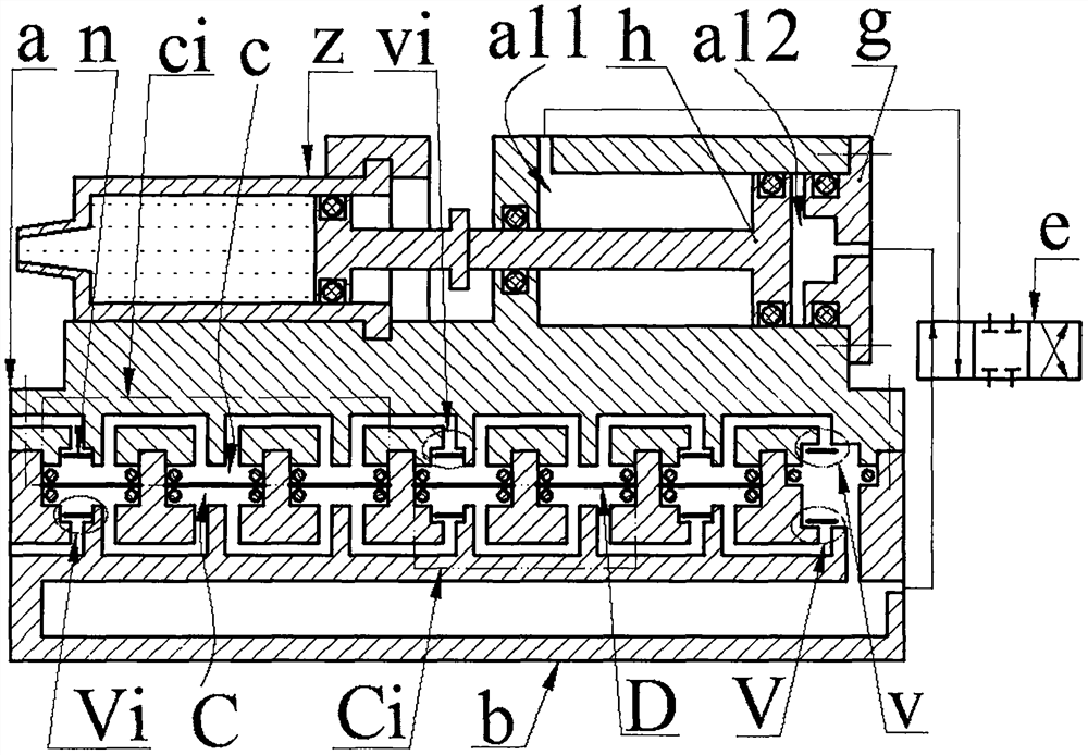
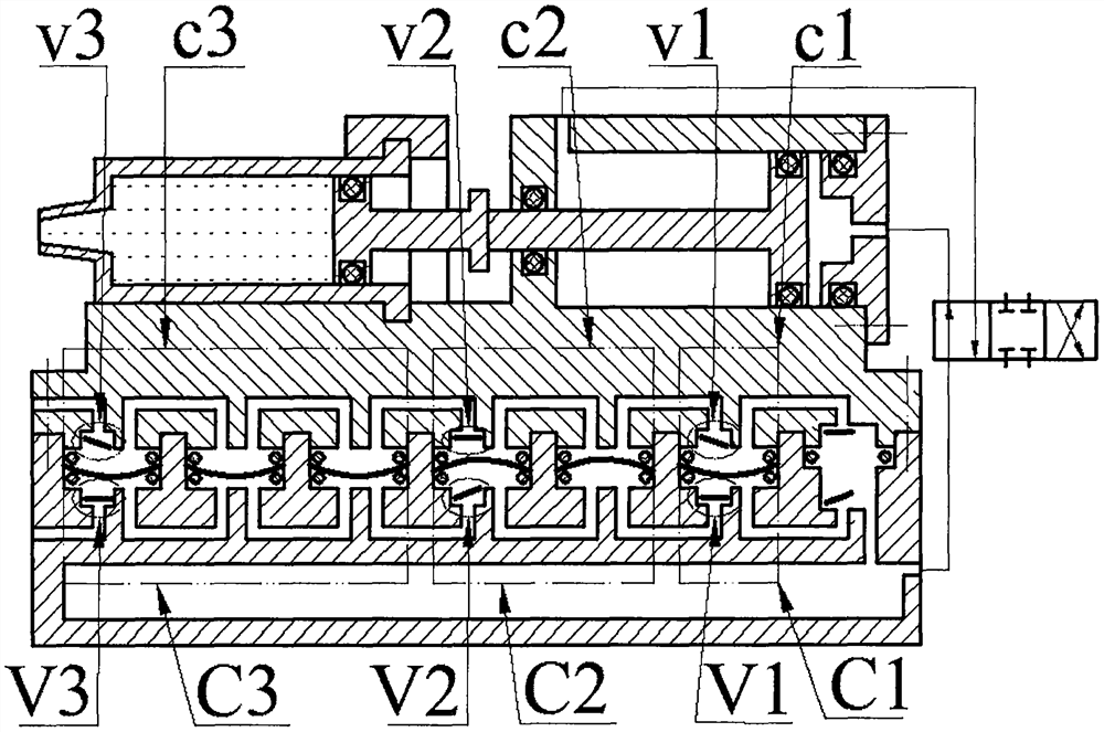
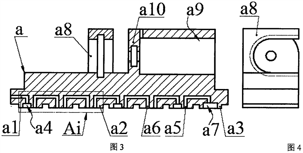
[0016] The top of the main body a is equipped with a syringe z, a cylinder chamber a9 and a baffle plate a8 with a chute, the center line of the cylinder chamber a9 is in the horizontal plane; the inside of the cylinder chamber a9 is covered with a main piston h, and the side wall of the cylinder chamber a9 The end is equipped with a cylinder head g; the main piston h divides the cylinder chamber a9 into a left chamber a11 and a right chamber a12; the syringe z is composed of a cartridge z1 and an auxiliary piston z2, and the auxiliary piston z2 is placed in the cartridge z1 and connected with the cartridge z1 constitutes the drug chamber z3, the ear plate z4 at one end of the cartridge z1 is placed in the chute of the baffle a8, and the infusion tube with a needle is installed at the other end; the push rod of the main piston h passes through the through hole on the left wall a10 of the cylinder chamber Extend out and lean against the push rod of the auxiliary piston z2; the b...


PUM


Abstract

The invention relates to a drug delivery device driven by gas stepwise compression, which belongs to the field of medical equipment. The main body is equipped with a syringe and a cylinder chamber. The main piston in the cylinder chamber divides the cylinder chamber into left and right chambers. The main piston push rod protrudes through the left wall of the cylinder chamber and leans against the push rod of the auxiliary piston of the syringe; the main body is installed in the On the base, the small boss of the main body is placed in the cavity of the box body. The boss of the main body is crimped in the body cavity of the base through the sealing ring. The driver is composed of two piezoelectric vibrators and ring gaskets. The piezoelectric vibrator consists of The substrate and the piezoelectric sheet are bonded together; the driver and the sealing ring form the upper and lower compression chambers with the main body and the base respectively. unit, the upper and lower compression units are connected in parallel; the left and right chambers are connected to the gas storage chamber through the air pipe and reversing valve; during operation, the deformation direction of the piezoelectric vibrator in the same body cavity group is the same, and the deformation direction of the piezoelectric vibrator in two adjacent body cavity groups is opposite .

Description

technical field [0001] The invention belongs to the field of medical equipment, and in particular relates to a drug delivery device driven by gas step-by-step compression. Background technique [0002] Injection mainly includes intravenous injection, intramuscular injection and subcutaneous injection. Intravenous injection is also called infusion drug administration. Most of the existing infusion devices are composed of infusion bottles, infusion tubes and infusion stands. This infusion mode will bring many problems in actual use: the flow rate is adjusted manually, and the flow control accuracy is not enough; the infusion bottle needs to be held high by others when the patient walks or goes to the toilet, which is inconvenient to move and the height of the infusion bottle is not high enough. Make the blood flow back; the patient or the nursing staff need to watch for a long time, if the infusion is not found in time, it may cause an accident; the liquid medicine is in cont...

Claims


Application Information

Patent Timeline
Patent Type & Authority Patents(China)
IPC IPC(8): A61M5/155A61M5/168
Inventor 郑佳佳王凯陈冰悦张江浩王淑云杨泽盟程光明
Owner ZHEJIANG NORMAL UNIVERSITY
Why Eureka
Try Eureka