Motion control method and device of laser cutting nozzle and computer device

A laser cutting and motion control technology, used in laser welding equipment, welding equipment, metal processing equipment, etc., can solve the problems of workpiece board surface warping, low cutting efficiency, board surface deformation, etc., to achieve smooth motion and ensure safety , the effect of improving safety

Active Publication Date: 2019-05-31
HANS LASER TECH IND GRP CO LTD +1
View PDF8 Cites 5 Cited by
  • Summary
  • Abstract
  • Description
  • Claims
  • Application Information

AI Technical Summary

Problems solved by technology

[0003] In the process of flat panel cutting, when the laser cutter wants to reach the target cutting point from the current cutting point, the laser cutter needs to be lifted up vertically at the current cutting point first, then do a translational movement along the horizontal direction, and finally descend vertically to reach the target The cutting point is used to ensure the safety of cutting. However, in the actual cutting process, the cutting efficiency of the above method is low. Therefore, the leapfrog method is used to improve the cutting efficiency.
[0004] However, no matter whether the leapfrog method is adopted or not, due to the thermal effect or the turning of the workpiece, the surface of the workpiece may be warped or the surface of the workpiece may be deformed to produce a slope, resulting in the inability to guarantee the safety of cutting

Method used


Image

  • Motion control method and device of laser cutting nozzle and computer device
  • Motion control method and device of laser cutting nozzle and computer device
  • Motion control method and device of laser cutting nozzle and computer device

Examples


Embodiment Construction

[0049] The following will clearly and completely describe the technical solutions in the embodiments of the present invention with reference to the accompanying drawings in the embodiments of the present invention. Obviously, the described embodiments are only some, not all, embodiments of the present invention. Based on the embodiments of the present invention, all other embodiments obtained by persons of ordinary skill in the art without creative efforts fall within the protection scope of the present invention.

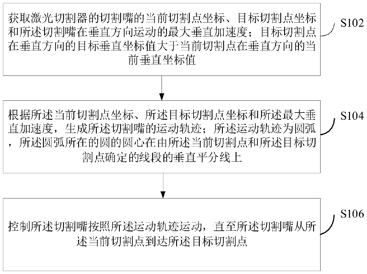
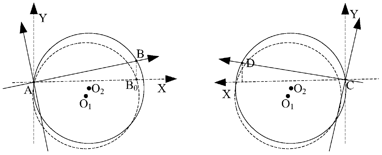
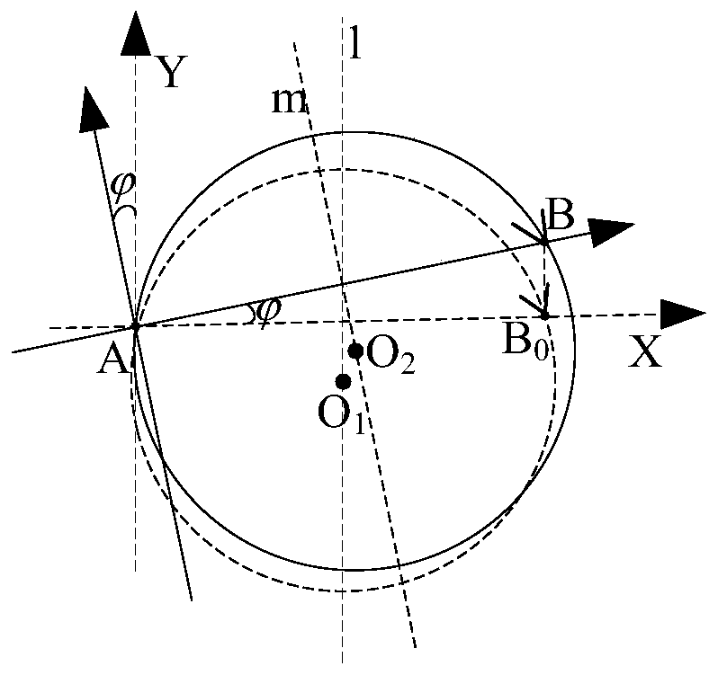
[0050] Such as figure 1 As shown, in one embodiment, a motion control method of a laser cutting nozzle is provided. The execution body of the motion control method of a laser cutting nozzle described in the embodiment of the present invention is a laser cutter. It should be noted that, in order to Well, the embodiment of the present invention will be described. In the following description and example process, the coordinate position of the current coordinate point...


PUM


Abstract

The embodiment of the invention discloses a motion control method and device of a laser cutting nozzle and a computer device. The method comprises the steps of obtaining the current cutting point coordinates, and the target cutting point coordinates of a cutting nozzle of a laser cutting device and the maximum vertical acceleration of motion of the cutting nozzle in the vertical direction; enabling the target vertical coordinate value of the target cutting point in the vertical direction to be larger than the current vertical coordinate value of the current cutting point in the vertical direction; according to the current cutting point coordinates, the target cutting point coordinates and the maximum vertical acceleration, generating the motion track of the cutting nozzle; enabling the motion track to be in an arc shape, wherein the circle center of the circle where the arc is located is located on the perpendicular bisector of a line determined by the current cutting point and the target cutting point; and controlling the cutting nozzle to move according to the motion track until the cutting nozzle reaches the target cutting point from the current cutting point. According to the above manner, the cutting efficiency and the safety are ensured to a certain degree.

Description

technical field [0001] The invention relates to the technical field of laser cutting, in particular to a motion control method, device and computer equipment of a laser cutting nozzle. Background technique [0002] Laser cutting is a non-contact processing method, which mainly generates a laser beam through a laser cutter, and transmits it to the laser head through an optical fiber, and melts the workpiece from the laser cutting nozzle. The laser cutter can move horizontally and vertically. [0003] In the process of flat panel cutting, when the laser cutter wants to reach the target cutting point from the current cutting point, the laser cutter needs to be lifted up vertically at the current cutting point first, then do a translational movement along the horizontal direction, and finally descend vertically to reach the target The cutting point is used to ensure the safety of cutting. However, in the actual cutting process, the cutting efficiency of the above method is low,...

Claims


Application Information

Patent Timeline
Patent Type & Authority Applications(China)
IPC IPC(8): B23K26/38B23K26/142B23K26/08
Inventor 宋俊杰封雨鑫陈焱高云峰
Owner HANS LASER TECH IND GRP CO LTD
Why Eureka
Try Eureka