
Gripper, in particular pneumatically actuated gripper in the form of a suction gripper or gripper jaws

A technology of clamps and clamps, applied in the field of pneumatically operated clamps, which can solve problems such as surface damage

Active Publication Date: 2019-05-31
FIPA控股有限(责任)公司
View PDF10 Cites 0 Cited by
  • Summary
  • Abstract
  • Description
  • Claims
  • Application Information

AI Technical Summary

Problems solved by technology

[0007] Furthermore, when using a gripper system for manipulating objects, it is unavoidable that the at least one gripping member of the gripper (a suction cup or a gripper with jaws when the gripper is designed as a suction gripper) comes into contact, This in some cases leads to damage to the surface of the object to be clamped in particular

Method used


Image

  • Gripper, in particular pneumatically actuated gripper in the form of a suction gripper or gripper jaws
  • Gripper, in particular pneumatically actuated gripper in the form of a suction gripper or gripper jaws
  • Gripper, in particular pneumatically actuated gripper in the form of a suction gripper or gripper jaws

Examples


Embodiment Construction

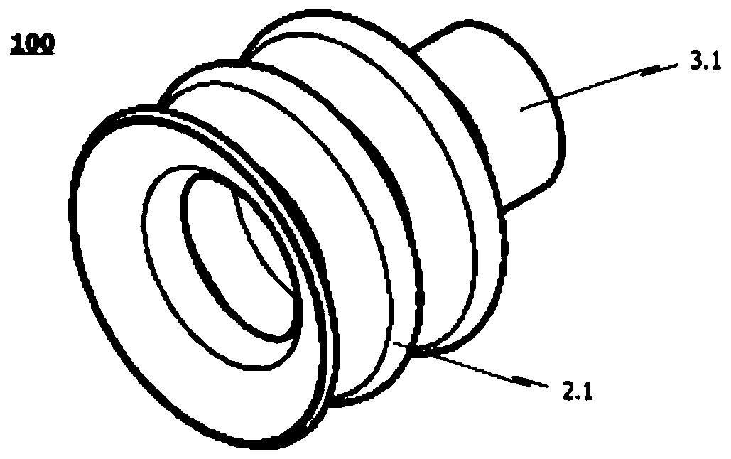
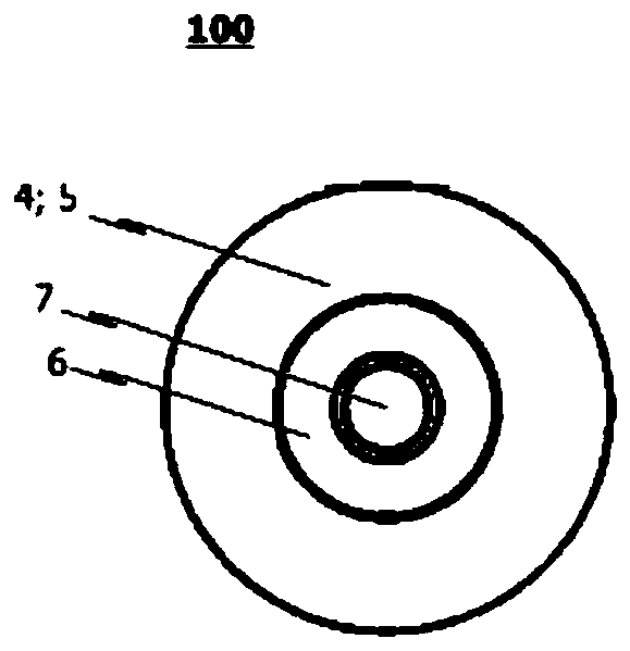
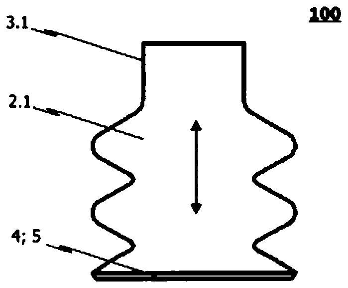
[0031] exist Figure 1a -c presents a first exemplary embodiment of the clamp 100 according to the invention in side view, isometric view and top view from below. This exemplary embodiment is designed in the form of a suction gripper.

[0032] The suction clamp has a generally elongated shape with a longitudinal axis. On the rear side, the suction gripper is equipped or can be equipped with any type of gripper holder, via which the gripper gripper can be fastened preferably detachably to a handling device not shown in the figures. The operating device enables the suction gripper to be moved and positioned, ie corresponding to various intended realizations. The operating device is in particular of the mechanical type and may comprise one or more electric and / or fluidic drives.

[0033] The suction clamp comprises a flexible suction cup 2.1, which serves as a clamping component, which is fastened with its rear end region on the clamp support (suction cup support 3.1). Prefera...


PUM


Abstract

The present invention relates to a gripper (100) and in particular a pneumatically operated gripper (100) in the form of a vacuum gripper or gripping tongs. The gripper (100) comprises a gripper holder (3.1, 3.2) via which the gripper (100) is preferably detachably connectable to a manipulator, robotic arm or the like. The gripper (100) further comprises at least one gripping member (2.1, 2.2) connected to the gripper holder (3.1, 3.2) and realized such that an object to be gripped or workpiece can be gripped by manipulating the at least one gripping member (2.1, 2.2). In order to achieve thegripper (100) being able to gently grip an object to be gripped, whereby both the object to be gripped as well as the at least one gripping member of the gripper are effectively protected against damage while the object to be gripped is being manipulated, the invention provides for the at least one gripping member (2.1, 2.2) to have a flocking (5) at least in the area which comes into contact withthe object to be gripped / workpiece during the manipulating of the at least one gripping member (2.1, 2.2).

Description

technical field [0001] The invention relates to a gripper, in particular a pneumatically operated gripper in the form of a suction gripper or pliers. Background technique [0002] The principle of such clamps is known in the prior art. As an example of this, DE 19 855 630 B4 is cited, which relates to a pneumatically operated gripper in the form of a pliers. As a further example, DE 20 2005 007145 U1 is cited, which relates to a gripping fixture for gripping and holding workpieces. [0003] Regardless of their design, grippers are often used in conjunction with industrial robots for manipulating different types of objects. Grippers designed as suction grippers are often required in order to grip objects, lift them up and transport them to different locations. For this purpose, the suction gripper often has a flexible suction cup which delimits a suction space which can be connected to a vacuum source and which has a suction opening in the surrounding front boundary region...

Claims


Application Information

Patent Timeline
Patent Type & Authority Applications(China)
IPC IPC(8): B25B11/00
CPCB25J15/00B25J15/0616B25J19/0075B25J15/0683B25J15/0023
Inventor 亨宁·施翰兹
Owner FIPA控股有限(责任)公司
Learn More