Air outlet device, air conditioning system and transportation tool

A technology for air-conditioning systems and vehicles, which is applied in transportation and packaging, air handling equipment, heating/cooling equipment, etc. It can solve the problems of dashboard visual conflicts, inability to achieve visual effects, and single function of the air outlet, so as to reduce development costs , Simple structure, free from ash falling effect

Pending Publication Date: 2019-05-31
NINGBO JOYSONQUIN AUTOMOTIVE SYST HLDG CO LTD
View PDF0 Cites 15 Cited by
  • Summary
  • Abstract
  • Description
  • Claims
  • Application Information

AI Technical Summary

Problems solved by technology

[0003] However, the function of the air outlet of the current car is single, and the main blade and the secondary blade are needed to guide the wind from left to right and up and down. The blades and secondary blades are generally exposed on the surface of the air outlet, which creates a large visual conflict with the instrument panel and cannot achieve hidden visual effects

Method used


Image

  • Air outlet device, air conditioning system and transportation tool
  • Air outlet device, air conditioning system and transportation tool
  • Air outlet device, air conditioning system and transportation tool

Examples


Embodiment 1

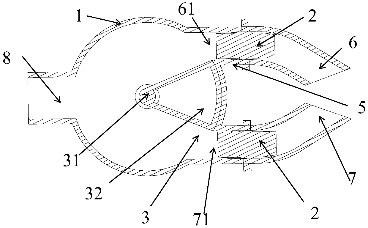
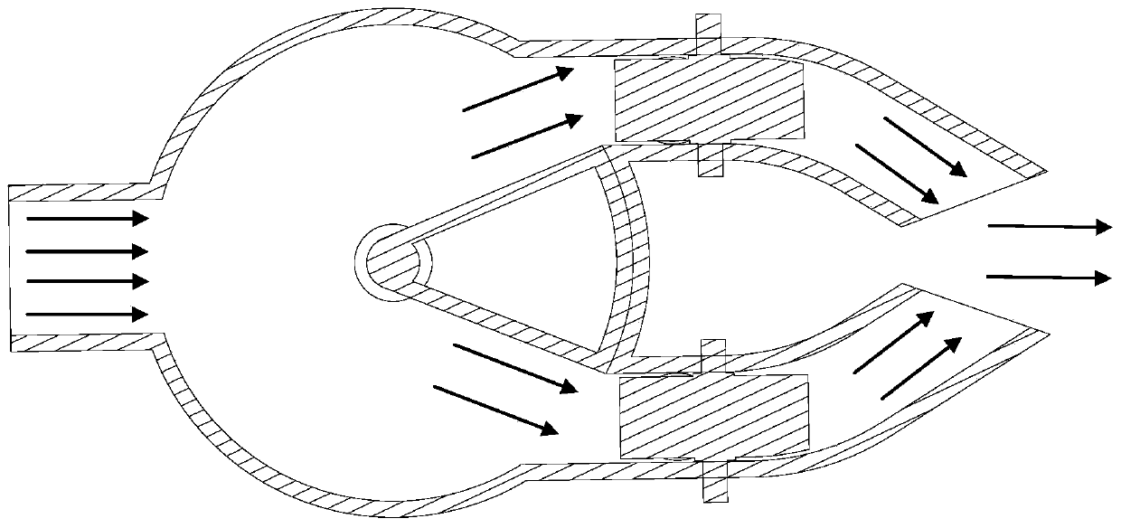
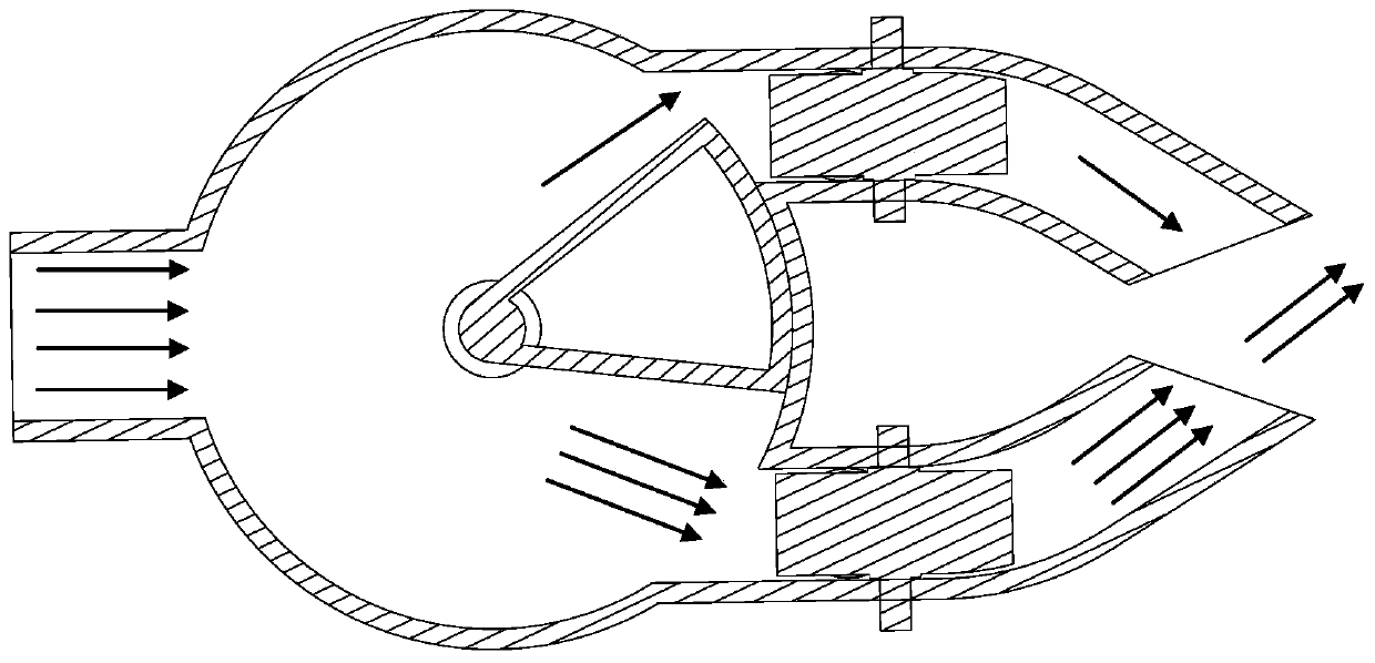
[0055] Please refer to Figure 1 to Figure 11 . figure 1 The cross-section in the cross-sectional view is parallel to the direction of fluid flow in the air outlet device, Figure 2 to Figure 7 Both are schematic diagrams in the direction of the section, Figure 8 to Figure 10 The section where the steering structure 2 in and figure 1 The cross-section in the cross-sectional view is vertical, Figure 2 to Figure 10 The direction of the black arrow in the figure refers to the flow direction of the fluid, and the number of arrows refers to the flow rate of the fluid. Embodiment 1 of the present invention provides an air outlet device, which includes a first channel 6 , a second channel 7 , an air guide structure 3 and a direction adjustment structure 2 . The first passage 6 has a first air inlet 61 and a first air outlet 62; the second passage 7 has a second air inlet 71 and a second air outlet 72; the air guide structure 3 is used to adjust the first air inlet 61 and The r...

Embodiment 2

[0081] The shape and structure of the first channel and the second channel in the air outlet device in the second embodiment are basically the same as those in the first channel and the second channel in the first embodiment, and the same structure adopts the same numbering, which will not be repeated here. , only the differences are described below.

[0082] Please refer to Figure 12 to Figure 23 . Figure 12 The cross-section in the cross-sectional view is parallel to the direction of fluid flow in the air outlet device, Figure 13 to Figure 18 Both are schematic diagrams in the direction of the section, Figure 13 to Figure 18 The section where the steering structure 4 in and Figure 13 The cross-section in the cross-sectional view is vertical, Figure 13 to Figure 18 The direction of the black arrow in the figure refers to the flow direction of the fluid, and the number of arrows refers to the flow rate of the fluid.

[0083] In this embodiment, the shape of the air ...

Embodiment 3

[0095] The shape and structure of the air guide structure in the air outlet device in the third embodiment are basically the same as those in the second embodiment, and the same structure uses the same number, so it will not be repeated here, and only the differences will be described below.

[0096] Please refer to Figures 25 to 28 . Both the first passage and the second passage in the air outlet device provided in this embodiment have two sections, a parallel section 63 and a bent section 64, the parallel section 63 is parallel to the total air inlet, and the bent section 64 is bent and set, and the direction is adjusted Structures are provided in the parallel section 63 .

[0097] In this embodiment, the centerlines of the two shielding parts of the wind guiding structure 10 are on the same straight line. The arc length of one of the shielding parts is smaller than the length of the third section, but the arc length is larger than the inner diameters of the first air inl...


PUM


Abstract

The invention provides an air outlet device, an air conditioning system and a transportation tool. The air outlet device comprises a first channel, a second channel, an air guide structure and direction adjusting devices. The first channel is provided with a first air inlet and a first air outlet; the second channel is provided with a second air inlet and a second air outlet; the air guide structure is used for adjusting the relative sizes of the first and second air inlets; the direction adjusting structures are arranged on the first channel and the second channel respectively so as to adjustthe first direction of outlet air of the first air outlet and the first direction of outlet air of the second air outlet.

Description

technical field [0001] The invention relates to the technical field of air outlets, in particular to an air outlet device, an air conditioning system and a vehicle. Background technique [0002] At present, for many means of transportation, the air-conditioning system is already a standard configuration, especially the air-conditioning device of a car has become one of the signs to measure whether the functions of the car are complete. In the design of the air-conditioning system of the car, the car ventilation system is composed of the air outlet and the air duct, which is responsible for sending the treated air to the car cab to realize the functions of cooling, heating, defogging and defrosting, and purifying the air. [0003] However, the function of the air outlet of the current car is single, and the main blade and the secondary blade are needed to guide the wind from left to right and up and down. The blades and secondary blades are generally exposed on the surface o...

Claims


Application Information

Patent Timeline
Patent Type & Authority Applications(China)
IPC IPC(8): B60H1/34
CPCB60H1/3414B60H2001/3478
Inventor 徐锦标苏长青
Owner NINGBO JOYSONQUIN AUTOMOTIVE SYST HLDG CO LTD
Why Eureka
Try Eureka