Control method of drive system, drive system and new energy vehicle

A new energy vehicle and drive system technology, applied in the automotive field, to avoid cost burden and cost consumption

Active Publication Date: 2019-05-31
SAIC MOTOR
View PDF6 Cites 42 Cited by
  • Summary
  • Abstract
  • Description
  • Claims
  • Application Information

AI Technical Summary

Problems solved by technology

However, the method of heating the battery with

Method used


Image

  • Control method of drive system, drive system and new energy vehicle
  • Control method of drive system, drive system and new energy vehicle
  • Control method of drive system, drive system and new energy vehicle

Examples


no. 1 example

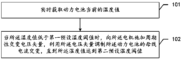
[0080] see figure 1 , which is a flow chart of a method for controlling a drive system provided in an embodiment of the present application.

[0081] Such as figure 1 As shown, the control method of the driving system provided in this embodiment includes:

[0082] Step 101: Obtain the current temperature value of the power battery in real time.

[0083] First, the application scenario of the method is described. The control method provided in this embodiment is applied to a motor controller of a drive system of a new energy vehicle. In addition to the motor controller, the drive system also contains other components, such as power batteries, motors, etc. The power battery contains multiple battery cells. The motor may be a three-phase motor. Of course, the drive system may also include other components, and the types and quantities of the components included in the drive system are not limited here.

[0084] It is understandable that the temperature of the power battery...

no. 2 example

[0103] see image 3 , which is a flowchart of another driving system control method provided in the embodiment of the present application.

[0104] Such as image 3 As shown, the control method of the driving system provided in this embodiment includes:

[0105] Step 301: Obtain the current temperature value of the power battery in real time.

[0106] In this embodiment, the implementation manner and purpose of step 301 are the same as those of step 101 in the foregoing embodiments, and the relevant description of step 301 may refer to the foregoing embodiments, and will not be repeated here.

[0107] Step 302: When the temperature value is lower than a first preset temperature threshold, apply a periodic alternating voltage vector to the motor, and use the voltage vector to modulate the alternating current of the busbar of the power battery.

[0108] It should be noted that, in practical applications, the voltage vector applied for the first time is a preset voltage vector...

no. 3 example

[0140] see Image 6 , which is a schematic structural diagram of a driving system provided in an embodiment of the present application.

[0141] Such as Image 6 As shown, the drive system provided by this embodiment includes:

[0142] Power battery 601, first temperature sensor 602, motor 603 and motor controller 604;

[0143] Wherein, the first temperature sensor 602 is used to detect the current temperature value of the power battery 601 in real time, and transmit the temperature value to the motor controller 604 in real time;

[0144] The motor controller 604 is configured to apply a periodic alternating voltage vector to the motor 603 when the temperature value is lower than a first preset temperature threshold, and use the voltage vector to modulate the bus current of the power battery 601 alternating until said temperature value reaches said first preset temperature threshold;

[0145] When the voltage vector is positive, the power battery 601 releases electric ener...


PUM


Abstract

The invention discloses a control method of a drive system, the drive system, and a new energy vehicle. The method obtains a current temperature value of a power battery in real time; when the temperature value is lower than a first preset temperature threshold, the temperature is raised to restore the drive capability of the drive system. A motor controller applies a periodic alternating voltagevector to a motor, the voltage vector is utilized to modulate bus current of a power battery to alternate, and during the process, the battery is driven to be repeatedly charged and discharged periodically to increase the temperature of the battery. Until the temperature value reaches a second preset temperature threshold, the battery is warmed to a desired operating temperature and the motor controller stops applying the voltage vector. Three-phase winding of the motor and three sets of bridge arms are used during the heating of the power battery. The recovery of the drive capability of the drive system is more economical without the need for additional external heating equipment. During the entire process of applying the voltage vector, the power battery is continuously and uniformly heated, the battery heating efficiency is very high, and rapid recovery of the drive capability is achieved.

Description

technical field [0001] The present application relates to the technical field of automobiles, in particular to a control method of a drive system, a drive system and a new energy vehicle. Background technique [0002] In the face of increasingly severe environmental problems and energy shortages such as petroleum, the promotion and use of new energy vehicles has become the main development trend of the current automotive industry. Compared with fuel vehicles, new energy vehicles have significant advantages in terms of energy saving and emission reduction. [0003] However, in the low temperature environment of new energy vehicles, components such as power batteries, motors and motor controllers in the drive system are easily affected by temperature, which limits the driving capability of the drive system and cannot provide sufficient power quickly, thus affecting the normal use of the car . [0004] At present, there are some technical methods that rely on heating equipmen...

Claims


Application Information

Patent Timeline
IPC IPC(8): B60L58/25H02P21/14
CPCY02T10/64Y02T10/70
Inventor 王东萃朱军王健王林武四辈伍宇飚孔金城
Owner SAIC MOTOR
Why Eureka
Try Eureka