Submersible (oil) multi-stage shaft bottom electromagnetic heating device

An electromagnetic heating device and an electromagnetic heater technology, which are applied in wellbore/well components, mining fluids, earthwork drilling and mining, etc., can solve problems such as huge supporting facilities, low heat utilization rate, and no specific requirements for ground space, and achieve improved Safety and reliability, effect of improving heat utilization

Pending Publication Date: 2019-05-31
安徽物迅科技有限公司 +1
View PDF0 Cites 2 Cited by
  • Summary
  • Abstract
  • Description
  • Claims
  • Application Information

AI Technical Summary

Problems solved by technology

[0008] The invention aims to solve the problems of low heat utilization rate, huge supporting facilities, and easy oil reservoir pollution caused by chemical flooding in the traditional heavy oil well production process.
[0009] According to the key points of traditional thermal recovery technology and the national deep-sea combustible ice mining technology requirements, the present invention provides a submersible (oil) multi-stage bottomhole electromagnetic heating device. The content of the invention is installed at the bottom of the well without specific requirements for ground space. , to solve the outstanding problems of land acquisition difficulties and small offshore platform space

Method used


Image

  • Submersible (oil) multi-stage shaft bottom electromagnetic heating device
  • Submersible (oil) multi-stage shaft bottom electromagnetic heating device
  • Submersible (oil) multi-stage shaft bottom electromagnetic heating device

Examples


Embodiment Construction

[0029] The electromagnetic heating device and method for seabed combustible ice mining of the present invention will be further described in detail below in conjunction with the accompanying drawings and specific embodiments.

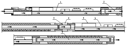
[0030] figure 1 The relationship between the connection of electromagnetic heating devices between multiple stages is given in detail. The specific structure includes: first-stage electromagnetic heating controller (1), heating element (2), oil pipe short connection (3), short protection pipe (4), secondary Level electromagnetic heating controller (6). The first-stage electromagnetic heating device (composed of the first-stage electromagnetic heating controller (1) and the heating element (2)) and the secondary electromagnetic heating device (the secondary electromagnetic heating controller (6) and the heating element (2)) For series connection, the number of secondary heating devices can be increased according to the power requirements of the heating ...


PUM


Abstract

The invention provides a submersible (oil) multi-stage shaft bottom electromagnetic heating device, and belongs to the field of production of submarine natural gas (combustible ice) and viscous oil. When a depressurization method is adopted for mining the submarine combustible ice, after the combustible ice converted into a liquid enters a shaft, the combustible ice is easily formed in a secondaryhydrate along with the increase of the pressure, which is not conductive to mining; when the viscous oil is mined, the oil has high viscosity, poor mobility and large swabbing resistance, and even isunsuitable for mining. Therefore, a method of shaft bottom heating is adopted for heating the combustible ice and viscous oil which enter the shaft, so that the formation of the secondary hydrate ofthe combustible ice can be prevented, and the viscosity and swabbing resistance of the viscous oil are reduced by heating the viscous oil. The submersible (oil) multi-stage heating device (1) can adopt an oil-submersible electric pump cable, and no made-to-order power supply cable is needed; (2) can be arranged at a specific well section requiring heating; (3) can adopt a multi-stage method for increasing the stages of the heating device according to the needs of heating power; (4) can adjust the heat power density of a heating well section. The submersible (oil) multi-stage shaft bottom electromagnetic heating device has the advantages that the limitation of an existing shaft bottom heating method is overcome to the utmost extent, and a new shaft bottom heating tool and method are provided for reducing the mining energy consumption cost of an oil and gas well and meeting the technical requirements of specific well section heating.

Description

technical field [0001] The invention belongs to the field of exploitation of seabed natural gas (combustible ice) and heavy oil wells, and in particular relates to a device and method for exploiting seabed natural gas (combustible ice) and heavy oil wells by means of electromagnetic heating, which is suitable for hydration of seabed natural gas (combustible ice) It is a tool and method for preventing the formation of secondary hydrates, reducing the viscosity of crude oil in heavy oil wells and improving its fluidity in the production of depressurization method. Background technique [0002] In the oil extraction of oil fields, heavy oil has special characteristics of high viscosity and high freezing point, and there are some technical difficulties in all aspects of development and application of heavy oil extraction. Heavy oil reservoir development technologies mainly include electric heating, steam huff and puff, steam flooding, adding viscosity reducer, etc. The combusti...

Claims


Application Information

Patent Timeline
Patent Type & Authority Applications(China)
IPC IPC(8): E21B43/24E21B43/01
Inventor 杨胡坤徐涛王海洪
Owner 安徽物迅科技有限公司
Why Eureka
Try Eureka