High-temperature and high-pressure sealing device

A sealing device, high temperature and high pressure technology, applied in the direction of engine sealing, engine components, mechanical equipment, etc., can solve problems such as sealing change, achieve the effect of simple structure, good versatility, and improve pressure transmission efficiency

Pending Publication Date: 2019-05-31
BEIJING RUILAIBO PETROLEUM TECH
View PDF0 Cites 1 Cited by
  • Summary
  • Abstract
  • Description
  • Claims
  • Application Information

AI Technical Summary

Problems solved by technology

The fluorine rubber O-ring has been proven to meet the test requirements in the traditional inner tank model, but the reduction of the wall thickness of the new inner tank model makes the transmission of internal and external pressure more convenient, and the combined effect of the internal and external forces of the model forms a The resultant moment acts on the sealing end face of the model. In the environment of high temperature and high pressure, the sealing of the inner tank model with a single O-ring becomes a problem.
[0004] The high-temperature and high-pressure sealing method of the present invention improves the current situation that the traditional sealing form cannot meet the high-temperature and high-pressure experimental environment. Gall model does not leak

Method used


Image

  • High-temperature and high-pressure sealing device
  • High-temperature and high-pressure sealing device

Examples


Embodiment Construction

[0021] The technical solution of this patent will be further described in detail below in conjunction with specific embodiments.

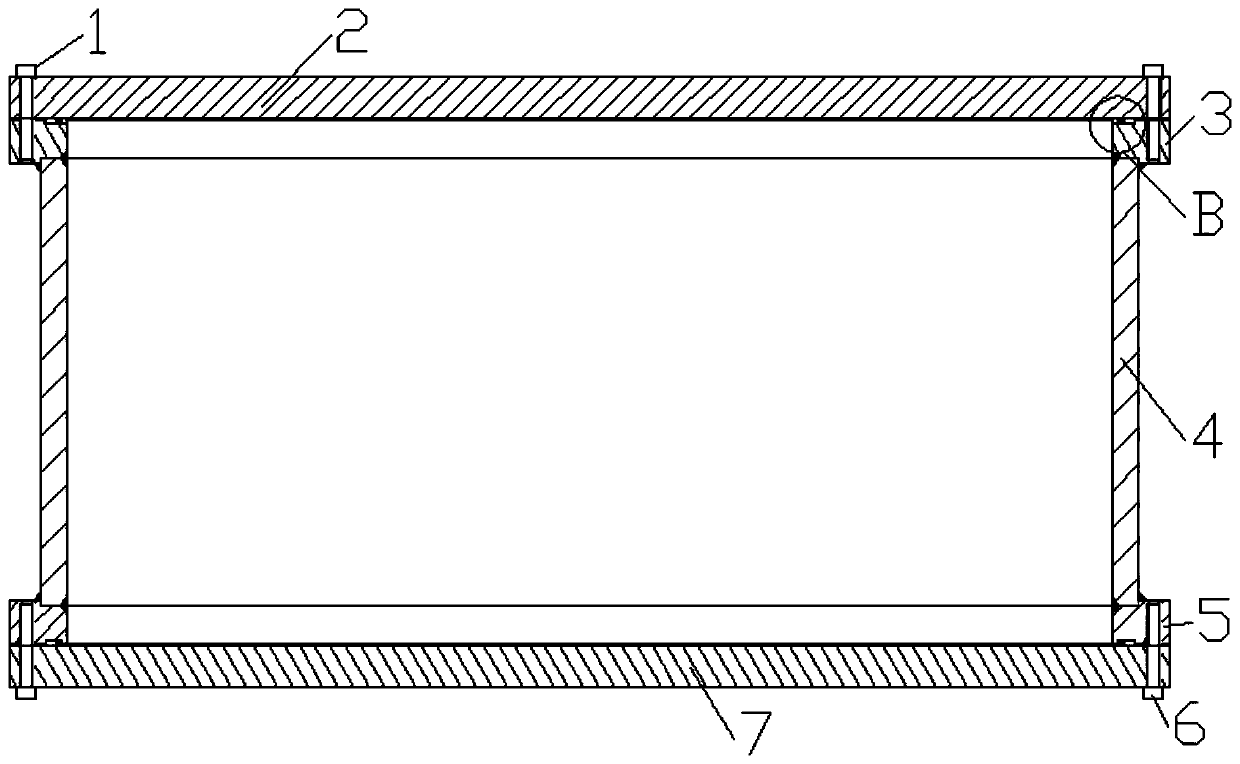
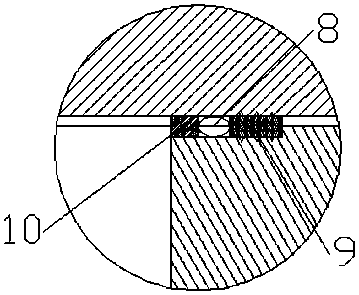
[0022] see Figure 1-2 , a high-temperature and high-pressure sealing device, including an upper kettle cover 2; an upper flange 3 is provided on the lower side of the bottom of the upper kettle cover 2; The set bolt 1 is threaded and fixedly connected, and a cylinder body 4 is provided on the lower side of the bottom; the cylinder body 4 is in the shape of a cylinder, and its interior is hollow, and its top and the upper flange 3 are connected by welding, and The lower side of the bottom is provided with a lower flange 5; the top of the lower flange 5 is connected to the cylinder body 4 by welding, and the lower side of the bottom is provided with a lower kettle cover 7; the lower kettle cover 7 and the lower flange 5 The second fastening bolts 6 are threaded and fixedly connected between them; the upper kettle cover 2, the lower kettle cover 7, ...


PUM


Abstract

The invention provides a high-temperature and high-pressure sealing device. The high-temperature and high-pressure sealing device comprises an upper kettle cover. An upper flange is arranged on the lower side of the bottom of the upper kettle cover. The upper flange and the upper kettle cover are fixedly connected through peripheral first fastening bolts in a threaded mode. Barrel bodies are arranged on the lower sides of the bottoms of the upper flange. A lower flange is arranged on the lower sides of the bottoms of the barrel bodies. A lower kettle cover is arranged on the lower side of thebottom of the lower flange. The lower kettle cover and the lower flange are fixedly connected through peripheral second fastening bolts in a threaded mode. The high-temperature and high-pressure sealing device is suitable for a novel square liner model and is particularly suitable for a sealing form of a built-in model of a thin-wall structure, so that the pressure transmission efficiency of the built-in model is improved.

Description

technical field [0001] The invention relates to the field of oil and gas exploration and development, in particular to a high-temperature and high-pressure sealing device. Background technique [0002] The square liner model is the core component of the heavy oil thermal recovery experimental device. In the traditional heavy oil thermal recovery experiment, the square liner model is often designed to be very heavy as the main experimental content. The reason for this design is that the square liner The tank model is placed in the hyperbaric chamber. When the hyperbaric chamber is pressurized, a higher pressure will be formed on the square inner tank model. If the wall thickness of the model is not enough, structural damage will easily occur. In the new experimental device for thermal recovery of heavy oil, the square liner is creatively set in a relatively light and thin form. The reason for this design is that in the new experimental device, we can pressurize the inside of ...

Claims


Application Information

Patent Timeline
Patent Type & Authority Applications(China)
IPC IPC(8): F16J15/06
Inventor 胡冠华刘文邢义良
Owner BEIJING RUILAIBO PETROLEUM TECH
Why Eureka
Try Eureka