Intelligent Optical Fiber Bidirectional Light Auxiliary Lighting System

A technology of auxiliary lighting and intelligent optical fiber, which is applied to the light guide, lighting device, non-electric lighting device and other directions of the lighting system, can solve the problems of low loss rate, heavy economic burden on residents, simple environmental requirements, etc. Lighting intensity, the effect of ensuring building safety

Active Publication Date: 2020-09-11
袁辰洲
View PDF7 Cites 0 Cited by
  • Summary
  • Abstract
  • Description
  • Claims
  • Application Information

AI Technical Summary

Problems solved by technology

[0004] The existing technology only uses optical fiber light guide for one-way transmission lighting, and there is no concept of two-way utilization, and the improvement of optical fiber lighting is mostly used for relatively limited applications such as changing the color of light, and does not make good use of the transmission distance of optical fiber lighting Long distance, low loss rate, simple environmental requirements, etc.
Some existing technologies have only explored the entertainment and artistic value of optical fiber for light guiding, but have not explored its practical value in engineering applications (such as life practice) deeply enough.
[0005] Some existing technologies introduce natural light into the room through the light pipe, but it cannot be used in two directions, and the light pipe is not easy to bend due to its large diameter, so it is not suitable for installation in the original rural buildings unless large-scale renovations are carried out on the original buildings , large-scale renovation not only poses a threat to the safety of the housing structure, but also costs too much and places a heavy economic burden on residents.

Method used


Image

  • Intelligent Optical Fiber Bidirectional Light Auxiliary Lighting System
  • Intelligent Optical Fiber Bidirectional Light Auxiliary Lighting System
  • Intelligent Optical Fiber Bidirectional Light Auxiliary Lighting System

Examples


Embodiment Construction

[0021] Below according to the attached Figure 1 to Figure 5 , give a preferred embodiment of the present invention, and give a detailed description, so that the functions and characteristics of the present invention can be better understood.

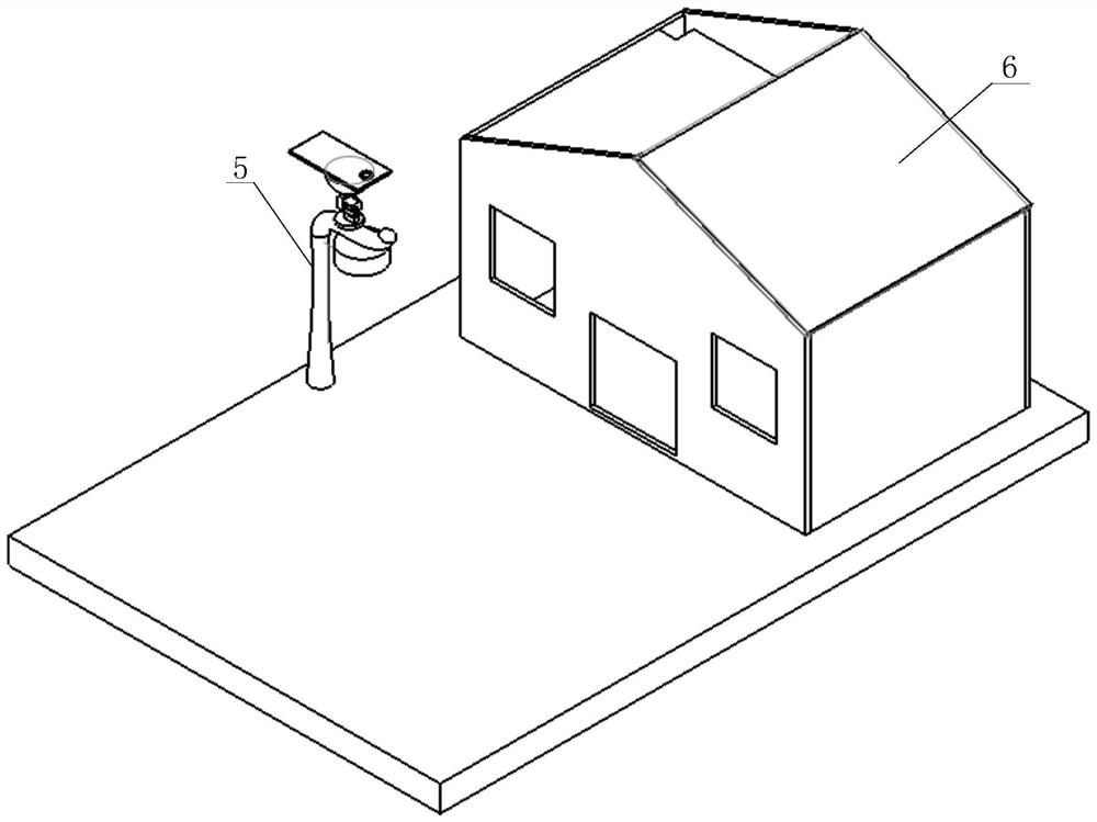
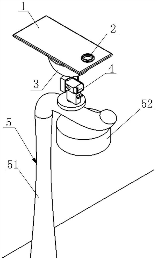
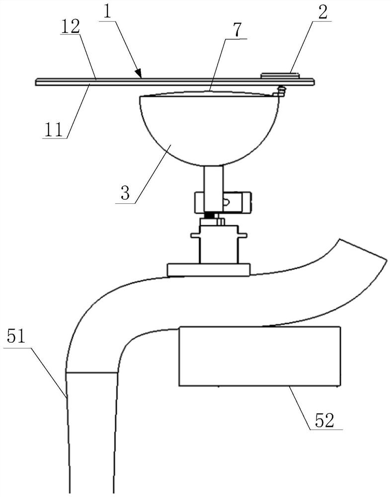
[0022] see Figure 1 to Figure 5 , a kind of intelligent optical fiber two-way light auxiliary lighting system of the embodiment of the present invention comprises a reflector 1, a reflector turning device 2, a transparent light collecting cover 3, an automatic light tracking device 4 and an optical fiber guide; The device 2 is fixed on the outside of the transparent light-collecting cover 3, the reflector 1 is connected with the transmission of the reflector turning device 2 and arranged above the transparent light-collecting cover 3, the lower surface of the reflector 1 forms a diffuse reflection surface 11; the transparent light-collecting The cover 3 is fixed on the road lamp 5 through the automatic light tracking device 4; the str...


PUM


Abstract

The invention provides a smart optical-fiber bi-directional ray auxiliary illuminating system. The system includes a reflection plate, a reflection plate steering device, a transparent light collection hood, an automatic light following device and an optical fiber catheter; the reflection plate steering device is fixed to the outer side of the transparent light collection hood, the reflection plate is in transmission connection with the reflection plate steering device and is arranged above the transparent light collection hood, and the lower surface of the reflection plate forms a diffuse reflection face; the transparent light collection hood is fixed to a street lamp through the automatic light following device; the street lamp includes a lamp pole, the optical fiber catheter penetratesthrough the interior of the lamp pole or is fixed to the outer side of the lamp pole, the first end of the optical fiber catheter is connected with the bottom of the transparent light collection hood,and the second end of the optical fiber catheter stretches into a first building and is connected with an illuminating device inside the building. By adopting the smart optical-fiber bi-directional ray auxiliary illuminating system, bi-directional ray utilization can be achieved, and a light source is fully utilized; meanwhile, the remolding size of current buildings can be reduced, and the safety of the buildings is ensured.

Description

technical field [0001] The invention relates to the field of lighting engineering, in particular to an intelligent optical fiber bidirectional light auxiliary lighting system. Background technique [0002] Optical fiber lighting refers to the transmission of light through optical fiber conductors, which can transmit light sources to any area. It is a high-tech lighting technology that has emerged in recent years. Some existing technologies focus on changing the color and other characteristics of light to improve its ornamental value, and some existing technologies focus on the merging and branching of optical fiber lighting. But all have not solved the auxiliary lighting application problem of fiber optic lighting in real life. [0003] Among the techniques for utilizing natural light, there is another light pipe technology: the light is introduced into the light pipe through an external light collector, and reflected into the room through multiple reflections in large-diam...

Claims


Application Information

Patent Timeline
Patent Type & Authority Patents(China)
IPC IPC(8): F21S11/00F21V3/02F21V3/04F21V5/04F21V7/04F21V8/00
Inventor 袁辰洲
Owner 袁辰洲
Why Eureka
Try Eureka