Geotechnical engineering drum type centrifuge device

A centrifuge and drum technology, applied in the field of centrifuges, can solve the problems of low transmission efficiency, belt slack or aging, large vibration, etc., and achieve the effects of high speed control accuracy, rapid start-up and stable operation

Pending Publication Date: 2019-06-04
GENERAL ENG RES INST CHINA ACAD OF ENG PHYSICS
View PDF5 Cites 1 Cited by
  • Summary
  • Abstract
  • Description
  • Claims
  • Application Information

AI Technical Summary

Problems solved by technology

This method of mechanical connection realizes connection or separation when the centrifuge is running at high speed, which is prone to large vibrations
[0007] The main drive system (drive model tank) of the traditional drum centrifuge basically adopts a pulley drive system, and its transmission characteristics lead to relatively low transmission efficiency, and the belt may slack or age under long-term operation, which will affect the centrifuge. Speed ​​stability and control accuracy

Method used


Image

  • Geotechnical engineering drum type centrifuge device
  • Geotechnical engineering drum type centrifuge device
  • Geotechnical engineering drum type centrifuge device

Examples


Embodiment 1

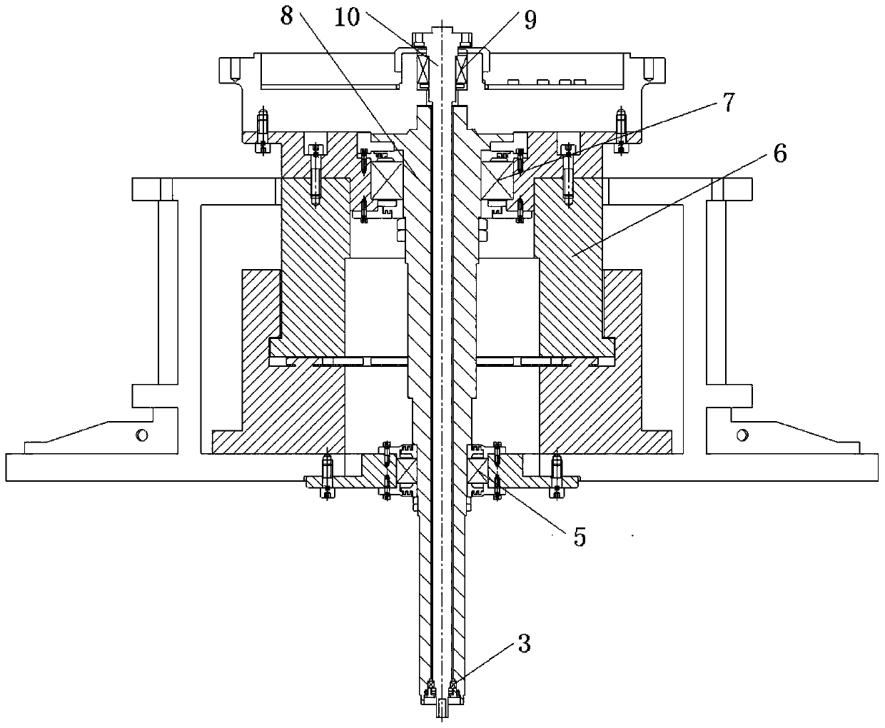
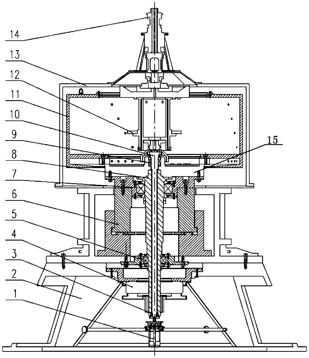
[0023] Example 1, such as figure 1 and figure 2 Shown:

[0024] A geotechnical drum centrifuge device comprising

[0025] An outer shaft 8; the outer shaft 8 is a hollow shaft, and the outer shaft 8 is used to drive the model groove 11 to rotate;

[0026] The inner shaft 10; the inner shaft 10 is installed inside the outer shaft 8, the inner shaft 10 is driven by the inner shaft motor 1, and the inner shaft 10 is used to drive the actuator platform 12 to rotate; the outer shaft 8 does not contact the inner shaft 10, and the outer shaft 8 and The inner shaft 10 is coaxially set;

[0027] The outer shaft motor 4 is a direct drive motor, and the outer shaft 8 passes through the outer shaft motor 4 and is driven by the outer shaft motor 4; the outer shaft 8 and the inner shaft 10 realize their synchronous or asynchronous motion through a cross-coupling control method.

[0028] The outer shaft motor 4 in this application adopts a high-power direct-drive motor; the inner shaft ...

Embodiment 2

[0032] Example 2, such as figure 1 and figure 2 Shown:

[0033] The difference between this embodiment and embodiment 1 is:

[0034] The centrifuge device also includes a cylindrical roller bearing for radially supporting the outer shaft 8, and a vertical thrust sliding bearing 6 for radially supporting the outer shaft 8 and axially supporting the rotating body.

[0035] In this embodiment, the rotating body includes a model groove 11, an actuator platform 12, inner and outer shafts, etc.;

Embodiment 3

[0036] Example 3, such as figure 1 and figure 2 Shown:

[0037] The difference between this embodiment and embodiment 2 is:

[0038] The outer wall of the outer shaft 8 is fixedly connected with the thrust head of the vertical thrust sliding bearing 6, the bearing seat of the vertical thrust sliding bearing 6 is fixed on the base 2, and the bottom of the model groove 11 is fixedly connected with the thrust head of the vertical thrust sliding bearing 6 .

[0039] In this embodiment, preferably, the outer shaft is fixedly connected to the model groove through the instrument cabin 15, and an instrument cabin 15 and a connecting piece are also arranged between the bottom of the model groove 11 and the thrust head of the vertical thrust sliding bearing 6. Such a design is In order to better cooperate with the installation of the model groove 11 and the vertical thrust sliding bearing 6 and the cable arrangement of the equipment, etc.


PUM


Abstract

The invention discloses a geotechnical engineering drum type centrifuge device, which includes an outer shaft and an inner shaft. The outer shaft is a hollow shaft, and used for driving a model grooveto rotate; the inner shaft is installed inside the outer shaft, driven by an inner shaft motor, and used for driving an actuator platform to rotate; the outer shaft and the inner shaft do not touch,and the outer shaft and the inner shaft are arranged on the same axis; the outer shaft motor is a direct drive motor, and the outer shaft passes through the outer shaft motor and is driven by the outer shaft motor; and synchronous or asynchronous motion of the outer shaft and the inner shaft is achieved through a cross coupling control method. According to the geotechnical engineering drum type centrifuge device, the outer shaft is directly driven by the direct drive motor, and the characteristics of rapid start, high rotating speed control accuracy, stable operation and the like are achieved;and synchronous or asynchronous motion of the outer shaft and the inner shaft is achieved through the cross coupling control method, and the vibration effect caused by synchronization of mechanical connection (a clutch) can be avoided.

Description

technical field [0001] The invention belongs to the technical field of centrifuges, and in particular relates to a geotechnical drum type centrifuge device. Background technique [0002] The drum centrifuge drives the ring-shaped model tank to rotate at high speed through a high-power motor, providing a centrifugal acceleration N times the acceleration of gravity g. It can be used to simulate pipelines, wave models and other model tests that require a large test plane space. Its outstanding advantage lies in the model tank. It can provide continuous and homogeneous samples with a large test space that is not affected by boundary effects; compared with arm centrifuges, drum centrifuges have a smaller rotation radius but faster rotation speeds, providing higher The centrifugal acceleration can simulate a larger prototype size in the ring direction, so it has irreplaceable technical advantages. Drum centrifuges are more and more widely used in geotechnical engineering, coastal ...

Claims


Application Information

Patent Timeline
Patent Type & Authority Applications(China)
IPC IPC(8): B04B9/02B04B9/08B04B9/10
Inventor 程发斌黎启胜王小龙洪建忠张鹏韩海军
Owner GENERAL ENG RES INST CHINA ACAD OF ENG PHYSICS
Why Eureka
Try Eureka