Floating ball valve

A technology of floating ball valves and ball valves, applied to valve devices, engine components, cocks including cut-off devices, etc., to achieve low production costs, self-cleaning sealing surfaces, and good sealing performance

Inactive Publication Date: 2019-06-04
李伟彦
View PDF0 Cites 0 Cited by
  • Summary
  • Abstract
  • Description
  • Claims
  • Application Information

AI Technical Summary

Problems solved by technology

In addition, even if the seat ring is separated from the valve body, it will cause slippage at the part that supports the valve body

Method used


Image

  • Floating ball valve
  • Floating ball valve

Examples


Embodiment Construction

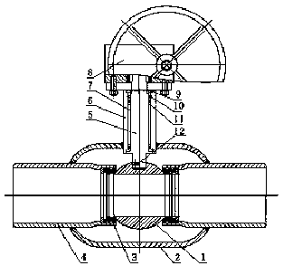
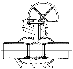
[0008] A floating ball valve, the ball valve includes a ball 1, a valve body 2, a valve seat 3, a joint 4, a valve stem 5, a shaft sleeve 6, a wear-resistant sheet 7, a motor 8, a gasket 9, a sealing ring 10, and a wear-resistant layer 11 and spring 12, the valve body 2 and the valve seat 3 are connected to each other, the ball 1 is set on the valve seat 3, the joint 4 is connected to the valve seat 3, and the valve stem 5 is vertical Placement, one end of the valve stem 5 is connected to the spring 12, and connected to the ball 1, and the other end is connected to the motor 8, the outer side of the valve stem 5 is provided with a wear-resistant sheet 7 and a wear-resistant layer 11, the described A shaft sleeve 6 is arranged outside the wear-resistant layer 11 .

[0009] The above embodiments are only used to illustrate the present invention rather than limit the technical scheme described in the present invention; therefore, although the present description has described the...


PUM


Abstract

The invention relates to a floating ball valve. The ball valve comprises a ball body, a valve body, a valve seat, a joint, a valve rod, a shaft sleeve, a wear-resistant sheet, a motor, a gasket, a sealing ring, a wear-resistant layer and a spring, wherein the valve body and the valve seat are connected with each other, the ball body is arranged on the valve seat, the joint is connected to the valve seat, the valve rod is vertically placed, one end of the valve rod is connected with the spring and is connected to the ball body, the other end of the valve rod is connected to the motor, the wear-resistant sheet and the wear-resistant layer are arranged on the outer side of the valve rod, and the shaft sleeve is arranged outside the wear-resistant layer. The floating ball valve has the advantages that the structure is simple, the sealing performance is good, the sealing surface is self-cleaned, opening and closing are convenient, friction is small, the opening torque is small, operation isstable, the production cost is low, and the service life is long.

Description

technical field [0001] The invention relates to a pipeline valve, in particular to a floating ball valve. Background technique [0002] A ball valve that closes the sliding gap around the valve body by pressing the seat ring against the valve body (ball) inserted into the valve chamber, and cuts off the communication between the valve chamber and the ball through the above-mentioned sliding gap (called a metal contact ball valve) Among them, when opening and closing the valve portion, the seat ring is separated from the valve body to reduce the operating torque of the valve (for example, refer to Patent Document 1). In the ball valve disclosed in Patent Document 1, the valve seat ring has a piston structure, and the valve body is pressed to and separated from the valve body by fluid pressure. Two pressure chambers that apply fluid pressure to the seat ring in opposite directions are formed on the outer periphery of the seat ring. When fluid pressure is introduced into the ...

Claims


Application Information

Patent Timeline
Patent Type & Authority Applications(China)
IPC IPC(8): F16K5/06F16K5/08
Inventor 李伟彦
Owner 李伟彦
Why Eureka
Try Eureka