
Thermostatic trap

A steam trap and constant temperature technology, applied in steam traps, mechanical equipment, etc., can solve the problems of huge steam pressure, heavy feeling of adjustment, and increase the difficulty of precise adjustment. Effect

Inactive Publication Date: 2019-06-04
谭思捷
View PDF0 Cites 0 Cited by
  • Summary
  • Abstract
  • Description
  • Claims
  • Application Information

AI Technical Summary

Problems solved by technology

[0002] Pneumatic steam traps are usually adjustable steam traps, which are widely used in steam-water systems such as main steam, reheating, low-pressure bypass, and steam extraction of thermal power plants. The current adjustment is usually rough adjustment. The design has been worked hard, but the adjustment accuracy is still not able to achieve a satisfactory effect. At the same time, due to the huge pressure of the steam, the pressure difference between the upper and lower ends of the valve disc when it is adjusted up and down makes the adjustment feel very heavy, which increases the accuracy. Difficulty of adjustment

Method used


Image

  • Thermostatic trap
  • Thermostatic trap

Examples


Embodiment Construction

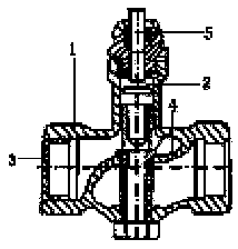
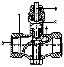
[0008] A thermostatic steam trap, the steam trap includes a valve body 1, a temperature sensing element 2, a filter screen 3, an elastic liner 4, and a telescopic assembly 5, the valve body 1 includes a water inlet and a water outlet, the The elastic liner 4 is set in the valve main body 1, the filter screen 3 is set at the water inlet and the water outlet, the telescopic assembly 5 is set on the upper part of the valve main body 1, and the telescopic assembly 5 is connected with a temperature sensor Components 2, the telescopic assembly 5 is in contact with the elastic liner 4, the elastic liner 4 is a rubber elastic liner, and the telescopic assembly 5 is a piston assembly.

[0009] The above embodiments are only used to illustrate the present invention rather than limit the technical scheme described in the present invention; therefore, although the present description has described the present invention in detail with reference to the above-mentioned embodiments, the ordina...


PUM


Abstract

The invention relates to a thermostatic trap. The trap comprises a valve body, a temperature sensing member, filter nets, an elastic liner and a telescopic assembly, the valve body comprises a water inlet and a water outlet, the elastic liner is arranged in the valve body, the filter nets are arranged on the water inlet and the water outlet, the telescopic assembly is arranged at the upper portionof the valve body, the telescopic assembly is connected with the temperature sensing member, the telescopic assembly is in contact with the elastic liner, the elastic liner is a rubber elastic liner,and the telescopic assembly is a piston assembly. The trap has the advantages that the structure is simple, the action is sensitive, the draining temperature is thermostatic, the trap is energy-saving and environmental-friendly, there exists no noise, the installing and maintaining are convenient, and gas discharging is automatically conducted.

Description

technical field [0001] The invention relates to an environmental protection device, in particular to a thermostatic drain valve. Background technique [0002] Pneumatic steam traps are usually adjustable steam traps, which are widely used in steam-water systems such as main steam, reheating, low-pressure bypass, and steam extraction of thermal power plants. The current adjustment is usually rough adjustment. The design has been worked hard, but the adjustment accuracy is still not able to achieve a satisfactory effect. At the same time, due to the huge pressure of the steam, the pressure difference between the upper and lower ends of the valve disc when it is adjusted up and down makes the adjustment feel very heavy, which increases the accuracy. Difficulty of adjustment. Contents of the invention [0003] In order to solve the above problems, the present invention provides a constant temperature drain valve with simple structure, sensitive action, constant temperature of...

Claims


Application Information

Patent Timeline
Patent Type & Authority Applications(China)
IPC IPC(8): F16T1/02
Inventor 谭思捷
Owner 谭思捷
Learn More