Precision magneto-optical alignment system and method for atomic gyro

An atomic gyroscope and alignment system technology, applied in the direction of measuring devices, instruments, etc., can solve the problems of low alignment accuracy, light field exit angle deviation, gyroscope performance impact, etc., and achieve the effect of enhancing control accuracy and improving accuracy

Inactive Publication Date: 2019-06-04
BEIJING AUTOMATION CONTROL EQUIP INST
View PDF4 Cites 2 Cited by
  • Summary
  • Abstract
  • Description
  • Claims
  • Application Information

AI Technical Summary

Problems solved by technology

However, at present, the atomic gyroscope mainly relies on machining accuracy and assembly technology to ensure the accuracy of optical-magnetic alignment. However, in actual situations, due to machining errors, the center of the coil winding circle is out of axis with the axis of the gyroscope, and the light-emitting components emit light. Surface processing errors lead to the deviation of the exit angle of the light field, and the low level of assembly technology leads to low alignment accuracy, which restricts the alignment accuracy of the internal driving light field and the main magnetic field of the atomic gyroscope, and directly affects the accuracy of the atomic ensemble control inside the atomic gyroscope. , has a great impact on the performance of the gyroscope, which restricts the further improvement of the gyroscope's accuracy

Method used


Image

  • Precision magneto-optical alignment system and method for atomic gyro
  • Precision magneto-optical alignment system and method for atomic gyro

Examples


Embodiment Construction

[0023] The present invention will be described in further detail below in conjunction with the accompanying drawings and specific embodiments.

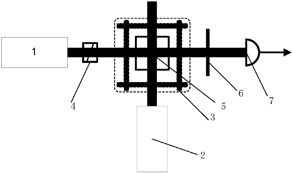
[0024] Such as figure 1 Said, a precise opto-magnetic alignment system of an atomic gyroscope, comprising a detection light source 1, a driving light source 2, a three-dimensional coil 3 and an atomic gas chamber 5, wherein the atomic gas chamber 5 is placed in the center of the three-dimensional coil 3, and the detection light source 1 Placed outside the three-dimensional coil 3 on one side of the atomic gas chamber 3, the photodetector 7 is placed on the other side of the three-dimensional coil 3 corresponding to the detection light source 1, so that the detection light source can be illuminated by the photodetector 7 after passing through the atomic gas chamber 5 Received; a polarizer 4 is placed on the optical path between the detection light source 1 and the atomic gas chamber 5, and an analyzer 6 is placed on the optical path be...


PUM


Abstract

The invention relates to the technical field of atomic gyro operation, and particularly discloses a precision magneto-optical alignment system and method for an atomic gyro. The precision magneto-optical alignment system for the atomic gyro comprises a detecting light source, a driving light source, a three-dimensional coil and an atomic gas chamber, wherein the atomic gas chamber is placed in thecenter of the three-dimensional coil; the detecting light source is placed outside the three-dimensional coil at one side of the atomic gas chamber; a photodetector is placed at the other side of thethree-dimensional coil corresponding to the detecting light source, and thus, irradiation of the detecting light source passes through the atomic gas chamber and then can be received by the photodetector; and the driving light source is placed in a direction vertical to the detecting light source, and light generated by the driving light source can pass through the atomic gas chamber. Accordingto the precision magneto-optical alignment system and the method for the atomic gyro, a driving light field and a main magnetic field can be ensured to be constantly in an alignment state, the operation precision of an atomic system inside the atomic gyro is enhanced, and a powerful help is provided for improvement of the atomic gyro precision and various performance indicators.

Description

technical field [0001] The invention belongs to the technical field of atomic gyroscope control, and in particular relates to a precise optical-magnetic alignment system and method for an atomic gyroscope. Background technique [0002] The atomic gyroscope is currently the smallest gyroscope that can achieve navigation-level accuracy. Its high precision, insensitivity to acceleration, stable scale factor, small size and low power consumption are considered to be the development direction of the next generation of gyroscopes. The atomic gyroscope achieves the purpose of measuring angular motion by detecting the different responses of atoms to the input angular rate of the sensitive axis under the action of the driving light field and the main magnetic field. Therefore, in the atomic gyroscope, it is required that the coordinate system of the driving light field coincides with the coordinate system of the main magnetic field. The error caused by the misalignment of the driving...

Claims


Application Information

Patent Timeline
Patent Type & Authority Applications(China)
IPC IPC(8): G01C25/00
Inventor 秦杰孙晓光万双爱刘建丰田晓倩
Owner BEIJING AUTOMATION CONTROL EQUIP INST
Why Eureka
Try Eureka