An indoor temperature and humidity field rapid prediction system and method

A prediction system, temperature and humidity technology, applied in the direction of prediction, manufacturing computing systems, neural learning methods, etc., can solve the problems of poor model calculation accuracy, time-consuming calculation, and inability to provide indoor temperature and humidity field information, etc.

Inactive Publication Date: 2019-06-04
CHONGQING UNIV
View PDF6 Cites 2 Cited by
  • Summary
  • Abstract
  • Description
  • Claims
  • Application Information

AI Technical Summary

Problems solved by technology

However, the establishment of these models often requires professional knowledge, and the calculation is time-consuming, which is not suitable for controller
The regional model and multi-regional model reduce the calculation time of the model by simplifying the calculation process of the CFD model, but the ca

Method used


Image

  • An indoor temperature and humidity field rapid prediction system and method
  • An indoor temperature and humidity field rapid prediction system and method
  • An indoor temperature and humidity field rapid prediction system and method

Examples


Embodiment 1

[0092] see figure 1 , a rapid prediction system for indoor temperature and humidity field, mainly includes a power drive module, p+1 temperature and humidity data acquisition modules, a data transmission module and a host computer.

[0093] The power drive module supplies power to the temperature and humidity data acquisition module.

[0094] The p temperature and humidity data acquisition modules are arranged in the grid positions corresponding to the maximum absolute values ​​of the p POD modes in the indoor CFD (computational fluid dynamics) model.

[0095] The main steps to calculate the POD mode of the CFD model are as follows:

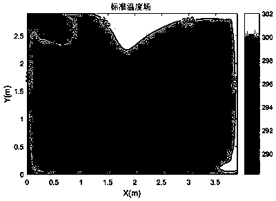
[0096] 1) Perform dynamic simulation on the CFD model. For the plane where the temperature and humidity need to be controlled to achieve thermal comfort, at t 1 ,t 2 ,...,t M Record M indoor temperature and humidity fields θ′ at each time t1 ,θ′ t2 ,…,θ′ tM .

[0097] 2) Calculate the fluctuation component θ of M indoor temperature and hu...

Embodiment 2

[0157] see Figure 2 to Figure 5 , a method for using a fast prediction system of indoor temperature and humidity field, mainly includes the following steps:

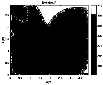
[0158] 1) Establish the CFD model of the indoor room, and use the POD model reduction technology to obtain p POD models. Arrange the temperature and humidity data acquisition module at the grid position corresponding to the maximum absolute value of each POD mode. Arrange a temperature and humidity data acquisition module outdoors.

[0159] 2) The temperature and humidity data collection module collects temperature and humidity data every Δt time, and transmits the data to the host computer through the data transmission module.

[0160] 3) Write and calculate the POD mode coefficient dynamic model and the POD mode coefficient optimal estimator in the host computer.

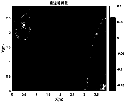
[0161] The optimal estimator of POD coefficient is obtained on the basis of establishing the dynamic model of POD mode, considering the influence of pro...


PUM


Abstract

The invention discloses an indoor temperature and humidity field rapid prediction system and method. The system mainly comprises a power supply driving module, p + 1 temperature and humidity data acquisition modules, a data transmission module and an upper computer. The temperature and humidity data acquisition module acquires temperature and humidity data. And the upper computer inputs the temperature and humidity data and the temperature and humidity predicted value into the POD mode coefficient dynamic model, calculates a POD mode coefficient, inputs the POD mode coefficient into the POD mode coefficient optimal estimator, and reconstructs an indoor temperature and humidity field. The method mainly comprises the steps that 1) the temperature and humidity data acquisition module acquirestemperature and humidity data; And 2) a dynamic model for calculating the POD mode coefficient and an optimal estimator for the POD mode coefficient are written into an upper computer. And 3) temperature and humidity data is predicted. And 4) a POD mode coefficient is calculated. 5) the POD mode coefficient is input into a POD mode coefficient optimal estimator, and establishing an indoor temperature and humidity field shown in the description; According to the indoor temperature and humidity field prediction method and system, the real-time performance is high, the precision is high, the anti-interference capability is high, and long-time prediction is achieved.

Description

technical field [0001] The invention relates to the technical field of temperature and humidity field prediction, in particular to a system and method for quickly predicting an indoor temperature and humidity field. Background technique [0002] Temperature and humidity play an extremely important role in the production and storage of food production, tobacco processing, biological products and other industries. If the temperature and humidity in the environment change greatly or exceed the standard range, the quality of the product will decline. Therefore, it is necessary to The temperature and humidity field of its environment is predicted, and then the temperature and humidity of the environment are controlled in advance. Although Computational Fluid Dynamics (CFD) can predict the temperature and humidity distribution, the model calculation is complex, time-consuming, and has poor real-time performance, which is not suitable for the design and analysis of controllers. The...

Claims


Application Information

Patent Timeline
IPC IPC(8): G06F17/16G06N3/08G06Q10/04G06Q50/04
CPCY02P90/30
Inventor 石欣陆未定赵莹王梨秦鹏杰刘昱岑田力李文昌廖亮罗志红朱琦徐淑媛朱家庆翟马强范智瑞张杰毅
Owner CHONGQING UNIV
Why Eureka
Try Eureka