Fiber structures and 3d preforms for composite parts
A fiber structure, prefabricated technology, used in textiles and paper, textiles, fabrics, etc.
- Summary
- Abstract
- Description
- Claims
- Application Information
AI Technical Summary
Problems solved by technology
Method used
Image
Examples
example 1
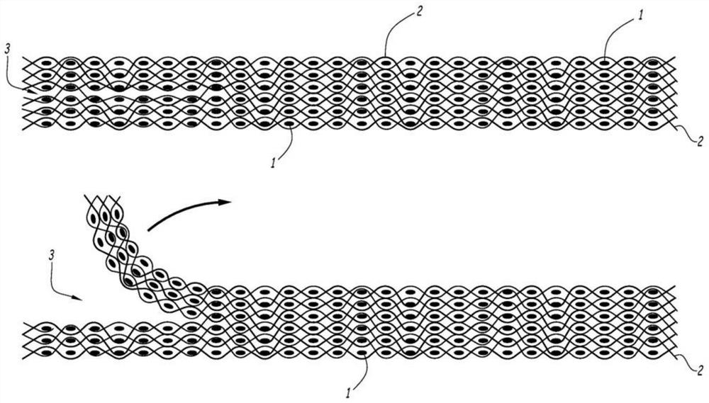
[0102] figure 1 6 consecutive horizontal planes of the weave of the fiber structure obtained by 3D weaving are shown, in which the weft threads 1 are visible in section and the warp threads 2 are shown longitudinally.
[0103] The fiber structure (on the left of the drawing) consists of 6 layers of weft threads and 12 layers of warp threads. On the right side of the figure, all layers of warp and weft threads are linked. On the left, the two central layers of weft threads are bonded together without warp threads in 7 vertical planes of the weft threads, where this is referred to herein as the debonding zone, ref. 3.
[0104] Fiber volume ratio: 50%.
[0105] Carbon yarn count in warp and weft: 3K
[0106] Thickness of structure (and preform): about 3mm.
[0107] The warp and weft yarns are carbon yarns impregnated with a polyepoxide resin that is approximately 7% by weight of the complete structure. The structure is unfolded and placed in a mold, passed through an oven to...
example 2
[0112] According to the principle of Example 1, it is possible to weave according to figure 2 (Left) Fiber structure comprising a first debonding zone 4 on the left and two debonding zones 5 and 6 on the right. This flat structure (left side of the diagram) can then be deployed in the form of a 3D deployment structure comprising 5 branches (right side of the diagram).
[0113] The warp and weft yarns are carbon yarns impregnated with a polyepoxide resin that is approximately 5% by weight of the complete structure. The structure is unfolded and placed in a mold, passed through an oven to soften the resin, and then cooled to produce a 3D preform. In the same mold or in another mold, the 3D preform will then be infiltrated or infused with the PEEK matrix to form the final part.
example 3
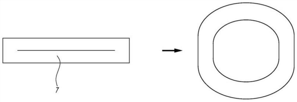
[0115] According to the same principle as Example 1, it is possible to weave according to image 3 (Left) Fibrous structure including central debonding zone 7 . This flat structure (left-hand drawing) can then be deployed in the form of a hollow 3D or hollow tubular structure (right-hand drawing).
[0116] The warp and weft yarns are carbon yarns impregnated with a polyamide resin that is approximately 10% by weight of the complete structure. The structure is unfolded and placed in a mold, passed through an oven to soften the resin, and then cooled to produce a 3D preform. In the same mold or in another mold, the 3D preform will then be infiltrated or infused with the PEEK matrix to form the final part.
[0117] Embodiments of debonding can be varied, for example, by forming the yarns into warps and combining both types of yarns in the same structure.
PUM
| Property | Measurement | Unit |
|---|---|---|
| thickness | aaaaa | aaaaa |
Abstract
Description
Claims
Application Information
 - R&D
- Intellectual Property
- Life Sciences
- Materials
- Tech Scout
- Unparalleled Data Quality
- Higher Quality Content
- 60% Fewer Hallucinations
Browse by: Latest US Patents, China's latest patents, Technical Efficacy Thesaurus, Application Domain, Technology Topic, Popular Technical Reports.
© 2025 PatSnap. All rights reserved.Legal|Privacy policy|Modern Slavery Act Transparency Statement|Sitemap|About US| Contact US: help@patsnap.com


