Cleaning head for electric rotating mop

A technology of electric rotation and cleaning head, applied in cleaning equipment, cleaning machinery, applications, etc., can solve the problems of low cleaning efficiency, inconvenient use, inability to vacuum and install and position, and achieve good cleaning effect and not easy to tear , the effect of not easy to fall off

Inactive Publication Date: 2019-06-07
阳珉
View PDF0 Cites 1 Cited by
  • Summary
  • Abstract
  • Description
  • Claims
  • Application Information

AI Technical Summary

Problems solved by technology

[0002] Currently on the market, electric rotary mops are relatively common. Usually, one or two round mops are used, which are driven by the motor inside the body to wipe the ground. , there is no pushing and scraping function, and the garbage cannot be gathered together like a normal mop, and the garbage cannot be taken away. In addition, because the motor is constantly rotating, the garbage will be scattered during the mopping process, resulting in the use of this type of mop When cleaning, the ground must be cleaned first, or cleaned with a vacuum cleaner, which is very inconvenient to use and the cleaning efficiency is low
[0003] In order to overcome the above shortcomings, in Chinese patent application 2017102149851, a "cleaning head and a cleaning tool using the cleaning head" is proposed. The cleaning blade with a curved rotation direction when cleaning sweeps the ground. Above the blade, there is an upper cover, and the center of the upper cover is provided with a through hole for installation, positioning and dust collection, which can collect garba

Method used


Image

  • Cleaning head for electric rotating mop
  • Cleaning head for electric rotating mop
  • Cleaning head for electric rotating mop

Examples


Embodiment 1

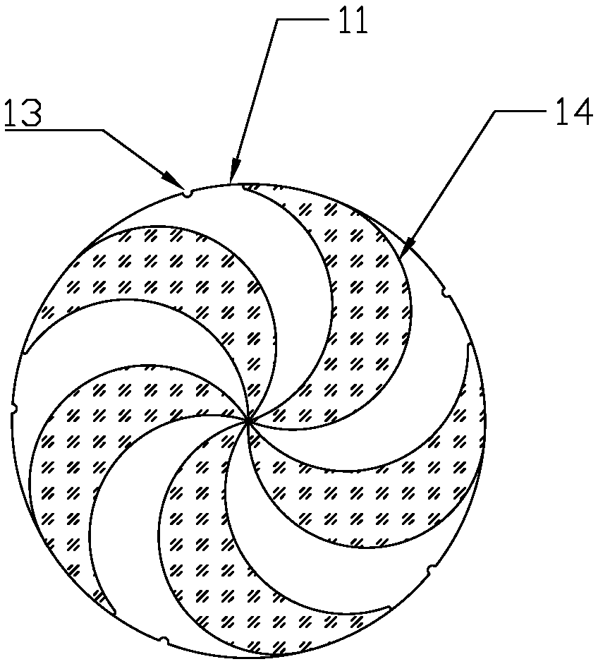
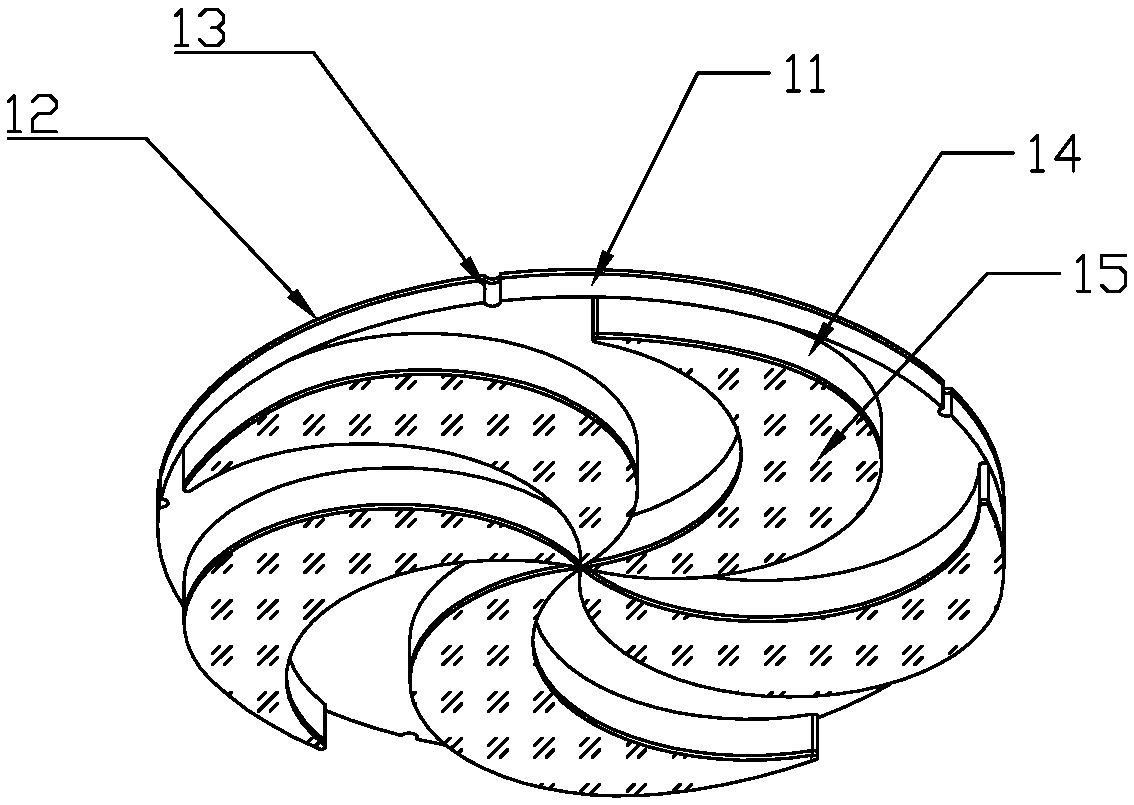
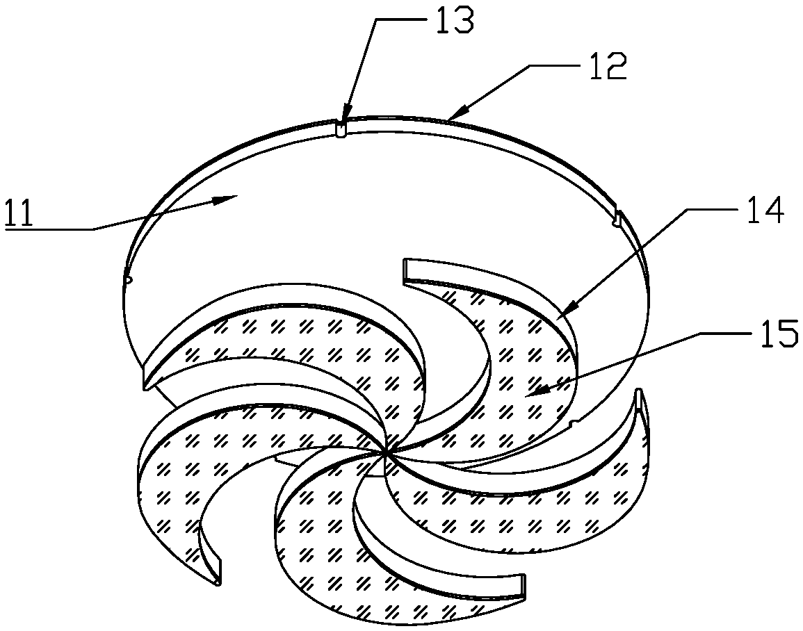
[0028] Embodiment 1: as figure 1 , figure 2 , image 3 As shown, the cleaning head includes a disc 11, a plurality of circumferential intervals are arranged below the disc 11, and cleaning bodies 14 curved in the same direction are arranged. The disc 11 and the cleaning body 14 can be sponges, sponges Composite materials, collodion, soft glue and other flexible materials, in this embodiment, the disc 11 and the cleaning body 14 are made of sponge composite material, the upper surface of the disc 11 is compounded with Velcro 12, the The lower surface of the cleaning body 14 is compounded with a wiping cloth 15, and the disc 11 and the cleaning body 14 are respectively formed by die-cutting, laser cutting, etc., and then glued together. The disc 11 and the cleaning body 14 can also be cast Molding, hot pressing, etc. are integrally formed, and then the upper surface of the disc 11 is glued with Velcro 12, and the lower surface of the cleaning body 14 is glued with a wiping cl...

Embodiment 2

[0029] Embodiment 2: as Figure 6 , Figure 7 , Figure 8 , Figure 9As shown, the cleaning head includes a disc 11, below the disc 11, a plurality of circumferentially spaced and curved cleaning bodies 14 are arranged, and the disc 11 and the cleaning body 14 are composed of Made of silica gel or rubber material, the disc 11 and the cleaning body 14 are integrally formed by casting, hot pressing, injection molding, etc. The lower surface of the cleaning body 14 is concave, and the concave part 16 is glued with a wiping cloth 15, The wiping cloth 15 can be a sponge composite cloth or other materials with water absorption and wear resistance, and the edge 17 of the concave part can be used as a scraper, and can also play the role of protecting the edge of the wiping cloth 15, and the wiping cloth 15 and the edge 17 cooperate Sweeping the ground can not only play a better cleaning effect, but also avoid the excessive contact area between the silica gel or rubber material and ...

Embodiment 3

[0030] Embodiment 3: as Figure 10 , Figure 11 As shown, an electric rotary mop using the cleaning head includes a mop rod 3 and a body 2. Two mounting plates 21 arranged side by side and opposite in direction of rotation are arranged below the body 2. The mounting plates 21 are formed by The motor in the body drives the rotation, and the bottom of the two mounting discs 21 is bonded with a cleaning head 1 by Velcro. The bending direction of the cleaning body of the two cleaning heads 1 is consistent with the rotation direction of the mounting disc 21; There is a water spraying device, and the water spraying device includes a miniature water pump controlled by a switch on the mop bar, and sprays water outwards through the water spray hole 24; at the rear of the mounting plate 21, a wiper installation plate 22 is provided, and the wiper installation plate The lower surface of 22 is bonded with wiping cloth 23 by Velcro.


PUM


Abstract

The invention discloses a cleaning head for an electric rotating mop. The cleaning head comprises a disc and a plurality of cleaning bodies which are arranged under the disc, distributed at intervalsin the circumferential direction and bent in the same direction, wherein the bending direction of the cleaning bodies is consistent with the rotating direction of the cleaning head during work; one ends of the cleaning bodies are connected to the center of the disc; the spacing between every two adjacent cleaning bodies is gradually reduced from outside to inside; garbage on the ground is wiped and gathered by the cleaning bodies into the gap between every two adjacent cleaning bodies and clamped and kept in the gap between every two adjacent cleaning bodies. The cleaning head can be directlyused for replacing a circular mop cloth used by an existing product without changing the existing electric mop, dirt can be gathered, and the garbage left on the ground is reduced.

Description

technical field [0001] The invention relates to the field of cleaning tools, in particular to a cleaning head for an electric rotary mop. Background technique [0002] Currently on the market, electric rotary mops are relatively common. Usually, one or two round mops are used, which are driven by the motor inside the body to wipe the ground. , there is no pushing and scraping function, and the garbage cannot be gathered together like a normal mop, and the garbage cannot be taken away. In addition, because the motor is constantly rotating, the garbage will be scattered during the mopping process, resulting in the use of this type of mop When cleaning, the ground must be swept clean first, or cleaned with a vacuum cleaner, which is very inconvenient to use and the cleaning efficiency is low. [0003] In order to overcome the above shortcomings, in Chinese patent application 2017102149851, a "cleaning head and a cleaning tool using the cleaning head" is proposed. The cleaning...

Claims


Application Information

Patent Timeline
IPC IPC(8): A47L11/283A47L11/40
Inventor 阳珉
Owner 阳珉
Why Eureka
Try Eureka