Road waste disposal area waste residue treatment device

A treatment device and a technology for a spoil yard, which is applied in the directions of grain treatment, dispersed particle separation, chemical instruments and methods, etc., can solve problems such as low reliability in use, laborious crushing, and environmental pollution in construction, so as to improve practical reliability and improve Work efficiency, ensure the effect of the construction process

Pending Publication Date: 2019-06-07
山西省交通环境保护中心站(有限公司)
View PDF0 Cites 6 Cited by
  • Summary
  • Abstract
  • Description
  • Claims
  • Application Information

AI Technical Summary

Problems solved by technology

[0002] As we all know, the road waste dump is a place for accumulating waste and soil generated during the road construction process. The waste disposal device for the road waste dump is a kind of waste disposal device used to treat the waste in the waste dump and reduce the occupation of waste. It is an auxiliary device that facilitates the management of the spoil ground, and it has been widely used in the fields of road construction and solid waste treatment; the existing waste disposal equipment for road spoil grounds includes a crushing box, and the interior of the crushing box is equipped with The working chamber is equipped with two groups of crushing rollers, and the rear end of the crushing box is provided with two sets of driving motors. The front output ends of the two driving motors extend into the working chamber from the rear It is connected with two sets of crushing rollers, the top of the crushing box is provided with a feeding hopper, and the bottom of the crushing box is provided with a discharge port; when the existing road waste disposal device is used, the

Method used


Image

  • Road waste disposal area waste residue treatment device
  • Road waste disposal area waste residue treatment device
  • Road waste disposal area waste residue treatment device

Examples


Example Embodiment

[0017] The specific embodiments of the present invention will be described in further detail below in conjunction with the drawings and embodiments. The following examples are used to illustrate the present invention, but not to limit the scope of the present invention.
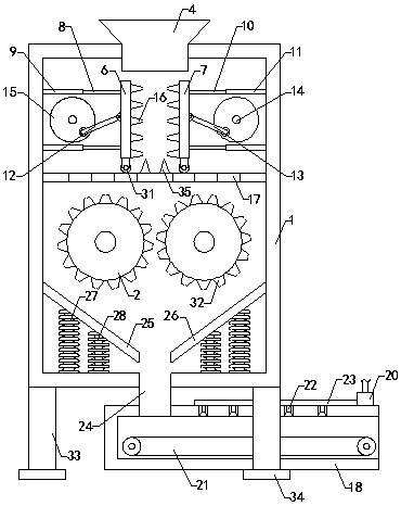
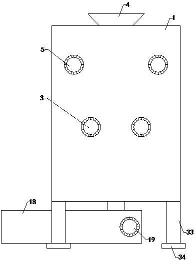
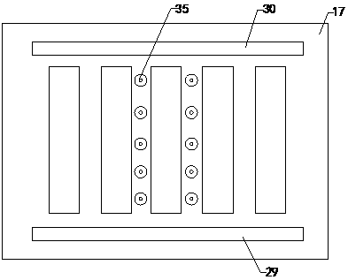
[0018] Such as Figure 1 to Figure 3 As shown, a road waste slag disposal device of the present invention includes a crushing box 1. A working cavity is arranged inside the crushing box 1, and two sets of crushing rollers 2 are arranged in the working cavity. The rear end of the crushing box 1 Two sets of drive motors 3 are provided. The front output ends of the two sets of drive motors 3 extend from the rear end of the crushing box 1 into the working cavity and are respectively connected to two sets of crushing rollers 2 in transmission. The top of the crushing box 1 is provided with a plus The hopper 4, the bottom end of the crushing box 1 is provided with a discharge port; it also includes two groups of firs...


PUM


Abstract

The invention relates to the technical field of solid waste treatment accessory devices, in particular to a road waste disposal area waste residue treatment device. The road waste disposal area wasteresidue treatment device can break large waste, damage to a smashing roller can be reduced, raised dust caused during waste slag guide-out operation can be treated, the pollution to the construction environment and nearby air environment can be avoided, practicability reliability is improved, meanwhile, blockage generated by waste slag in a work cavity can be effectively avoided, construction proceed is ensured, the device comprises a smashing box, two sets of smashing rollers, two driving motors, a loading hopper, a discharging opening, two first motors, a left breaking plate, a right breaking plate, four sets of left guide columns, four sets of left guide sleeves, four sets of right guide columns, four sets of right guide sleeves, a left driving rod, a right driving rod, a driving shaftand a rotating disc; the right end of the left breaking plate and the left end of the right breaking plate are provided with multiple sets of breaking teeth, and a grid plate, a conveying box, a conveying motor, an atomizing pump, a conveying device, an atomizing head, a communication pipe, a discharging pipe, a left guide conveying plate and a right guide conveying plate are further included.

Description

technical field [0001] The invention relates to the technical field of solid waste treatment attachments, in particular to a waste slag treatment device for road waste slag yards. Background technique [0002] As we all know, the road waste dump is a place for accumulating waste and soil generated during the road construction process. The waste disposal device for the road waste dump is a kind of waste disposal device used to treat the waste in the waste dump and reduce the occupation of waste. It is an auxiliary device that facilitates the management of the spoil ground, and it has been widely used in the fields of road construction and solid waste treatment; the existing waste disposal equipment for road spoil grounds includes a crushing box, and the interior of the crushing box is equipped with The working chamber is equipped with two groups of crushing rollers, and the rear end of the crushing box is provided with two sets of driving motors. The front output ends of the ...

Claims


Application Information

Patent Timeline
IPC IPC(8): B02C1/00B02C23/00B02C4/08B01D47/06
Inventor 曾厚波张凯李文军王振何晓雁张星王意龙
Owner 山西省交通环境保护中心站(有限公司)
Why Eureka
Try Eureka