Supercharge Your Innovation With Domain-Expert AI Agents!

Highly-intelligent automatic discharging transverse stamping device

A technology of automatic unloading and punching device, applied in the field of punching device, can solve the problems of low machining accuracy and low work efficiency, and achieve the effects of improving efficiency, high degree of automation, and increasing frictional force

Pending Publication Date: 2019-06-07
昆山筹胜机械科技有限公司
View PDF0 Cites 2 Cited by
  • Summary
  • Abstract
  • Description
  • Claims
  • Application Information

AI Technical Summary

Problems solved by technology

[0004] The purpose of the present invention is to solve the shortcomings of low work efficiency and low processing precision in the prior art, and propose a high-intelligence automatic unloading horizontal stamping device

Method used


Image

  • Highly-intelligent automatic discharging transverse stamping device
  • Highly-intelligent automatic discharging transverse stamping device
  • Highly-intelligent automatic discharging transverse stamping device

Examples


Embodiment 1

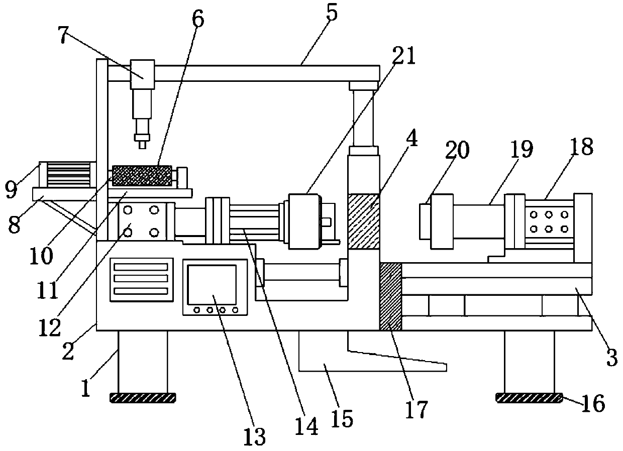
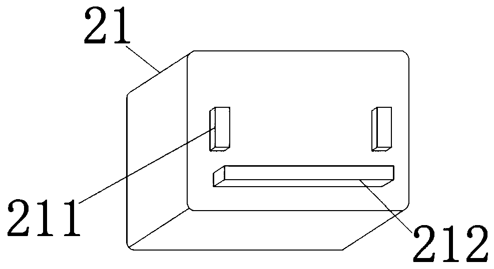
[0026] Embodiment 1, the bottom of the support foot 1 is provided with a silica gel pad 16, which plays a role of shock absorption and reinforcement, and the stability of the equipment is high. After the equipment is powered on, the servo motor drives the conveyor belt 6 to carry out batch transportation, which is transported by the previous process. Then, the whole process is controlled by the PLC controller 13, the model of the PLC controller 13 is S7-300, the slider 71 slides on the fixed rod 5, the lifting shaft 73 moves downward, and the product is clamped by the fetching claw 75, and then transported To the top of the load-bearing plate 212, after the lifting shaft 73 descends again, the product is placed on the load-bearing plate 212, and the retrieving claw 75 is released at the same time, the lifting shaft 73 slides upwards and recovers, and the material retrieving action of the product is completed.

Embodiment 2

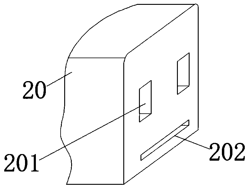
[0027] Embodiment 2, after the material retrieving is completed, the fixed gripper 211 clamps the product, the first cylinder 12 drives the first piston rod 14 to move to the right, passes through the inside of the stamping slot 4, and stops after reaching the processing station. The second cylinder 18 now drives the second piston rod 19 to move to the left, so that the punch 20 presses the product to stamp the product. During the stamping process, the fixed grippers 211 on both sides of the product go deep into the inside of the first groove 201, There is no collision between the mechanisms, and the load-bearing plate 212 snaps into the second groove 202 to simultaneously position the stamping, and the processing precision is high.

Embodiment 3

[0028] Embodiment 3: After the stamping is completed, the position of the punch 20 is restored, and the fixed gripper 211 is released. Since the product is deformed after stamping, the width of the bottom load-bearing plate 211 can no longer support the workpiece, and the workpiece automatically falls through the blanking chute. Hole 17 falls, is automatically slid down by unloading baffle plate 15 and carries out unloading, and reclaiming mechanism 7 actions carry out reclaiming next time afterwards.


PUM


Abstract

The invention relates to the technical field of punching devices, in particular to a highly-intelligent automatic discharging transverse stamping device. The highly-intelligent automatic discharging transverse stamping device overcomes the defects of low working efficiency and low machining precision in the prior art. The highly-intelligent automatic discharging transverse stamping device comprises supporting legs, wherein a first frame and a second frame are fixedly arranged on the top of the supporting legs in sequence; a first air cylinder is arranged on the top portion of the first frame;a first piston rod is arranged inside the first air cylinder; the other end of the first piston rod is connected to a punching base through a bolt; and a motor mounting plate is welded on one side ofthe first frame; and a servo motor is mounted on the top portion of the motor mounting plate. According to the highly-intelligent automatic discharging transverse stamping device, through the arrangement of structures such as the first air cylinder, the second air cylinder, a punch, the punching base, a discharging slot hole and a discharging baffle plate, a traditional vertical punching mode is changed into a transverse punching mode, and a product automatically falls after being machined and is discharged through the discharging baffle plate, so that the automation degree is high, and the punching efficiency is greatly improved.

Description

technical field [0001] The invention relates to the technical field of punching devices, in particular to a highly intelligent automatic unloading horizontal punching device. Background technique [0002] Stamping is a forming process that relies on presses and molds to apply external forces to plates, strips, pipes, and profiles to cause plastic deformation or separation, so as to obtain workpieces of the required shape and size. Stamping and forging belong to plastic processing. It is called forging, and the stamping blanks are mainly hot-rolled and cold-rolled steel plates and steel strips. Among the steel products in the world, 60-70% are plates, most of which are stamped into finished products. [0003] The stamping equipment in the prior art is all stamping in the vertical direction, and the product needs to be unloaded after the processing is completed, which reduces the work efficiency, and the traditional stamping device is not accurate enough in positioning, and th...

Claims


Application Information

Patent Timeline
Patent Type & Authority Applications(China)
IPC IPC(8): B21D22/02B21D43/00B21D45/06
Inventor 庞定勉
Owner 昆山筹胜机械科技有限公司
Features
  • R&D
  • Intellectual Property
  • Life Sciences
  • Materials
  • Tech Scout
  • Unparalleled Data Quality
  • Higher Quality Content
  • 60% Fewer Hallucinations
Learn More