Pipe electrode high-speed rotation self-suction type reflux electrolytic machining method

A technology of high-speed rotation and processing method, which is applied in the direction of electric processing equipment, electrochemical processing equipment, metal processing equipment, etc., and can solve the problems of complex sealing device, large processing accuracy and surface roughness

Inactive Publication Date: 2019-06-07
ANHUI UNIV OF SCI & TECH
View PDF7 Cites 4 Cited by
  • Summary
  • Abstract
  • Description
  • Claims
  • Application Information

AI Technical Summary

Problems solved by technology

Forward flow means that the electrolyte flows in from the center of the cathode tool, and flows out from the surroundings after passing through the processing gap. The advantage is that the sealing device is simple, but the processing accuracy and surface roughness are relatively large; Flow in around the hole and flow out through the center of the electrode tool. The advantages are stable processing and high precision, but the sealing device is complicated

Method used


Image

  • Pipe electrode high-speed rotation self-suction type reflux electrolytic machining method
  • Pipe electrode high-speed rotation self-suction type reflux electrolytic machining method

Examples


Embodiment Construction

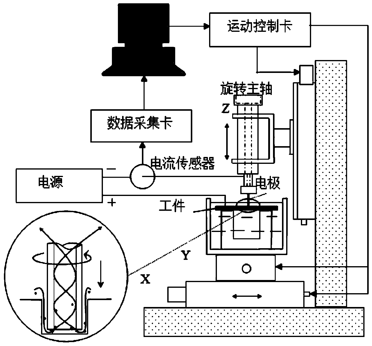
[0008] The high-speed motor with a hollow main shaft is fixed on a worktable that can move up and down. The tubular electrode is clamped on the hollow high-speed motor main shaft and connected to the negative pole of the power supply. The workpiece is fixed in the electrolyte tank, and the workpiece is connected to the positive pole of the power supply.

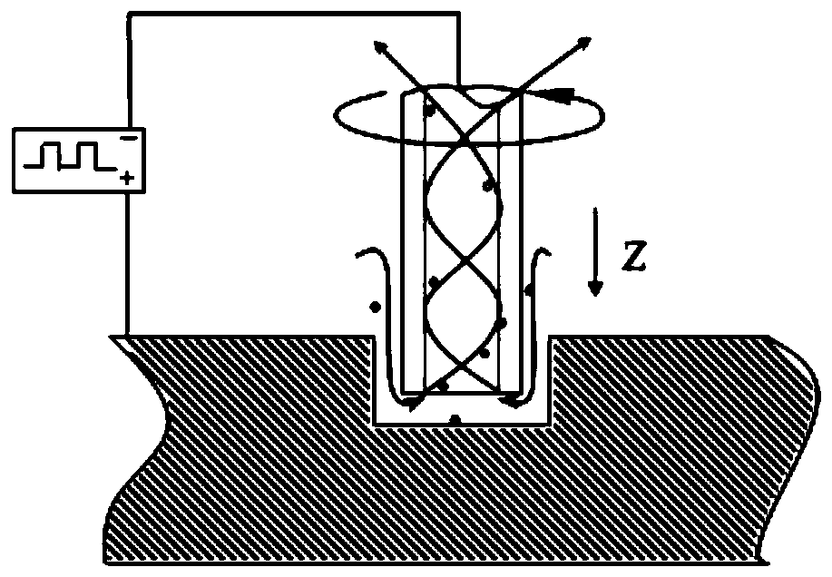
[0009] During electrolytic machining, the high-speed motor drives the tubular electrode to rotate at high speed. According to the knowledge of fluid mechanics, the electrolyte and electrolytic products will move upward at a certain speed inside the tubular electrode under the combined force of Coriolis force and centrifugal force, and finally pass through the hollow The end of the main shaft is discharged, and at the same time, the worktable drives the tubular electrode to move downward to process the hole.


PUM


Abstract

The invention relates to a pipe electrode high-speed rotation self-suction type reflux electrolytic machining method. A pipe electrode rotates at a high speed, the resultant force of Coriolis force and centrifugal force pumps and sucks electrolyte and an electrolysis product in electrolytic machining gaps to form reflux electrolytic machining. The pipe electrode is clamped on a motor rotating at ahigh speed, and the spindle of the motor is hollow; and when the motor rotates at a high speed, the motor drives the pipe electrode to rotate at a high speed to pump and suck electrolyte to form reflux, and the electrolyte and the electrolysis product are discharged out through an outlet in the tail end of the hollow spindle.

Description

technical field [0001] The invention belongs to the field of electrochemical processing technology, in particular to a tube electrode high-speed rotating self-priming counterflow electrolytic processing technology. Background technique [0002] During the electrolytic machining process, in the electrolytic machining gap, the electrolyte must have a certain flow rate, so as to take away the electrolytic products, heat and depolarization generated by the electrolytic machining inside the gap, so as to ensure that the electrolytic machining is carried out normally and stably without voids. Holes, scars and other faults caused by short circuit. At present, there are two situations for the flow direction of the electrolyte in the electrolytic machining hole: forward flow and reverse flow. Forward flow means that the electrolyte flows in from the center of the cathode tool, and flows out from the surroundings after passing through the processing gap. The advantage is that the sea...

Claims


Application Information

Patent Timeline
Patent Type & Authority Applications(China)
IPC IPC(8): B23H3/00B23H11/00
Inventor 李君黄绍服
Owner ANHUI UNIV OF SCI & TECH
Why Eureka
Try Eureka