High-voltage probe precision injection molding mold applied to X-ray equipment

A high-pressure probe and injection molding technology, applied in the field of injection molding molds, can solve problems such as low yield and production efficiency, and difficulty in achieving uniform injection molding, and achieve the effects of high yield, improved production efficiency, and improved molding performance.

Active Publication Date: 2019-06-07
宁波喆昊模具有限公司
View PDF8 Cites 0 Cited by
  • Summary
  • Abstract
  • Description
  • Claims
  • Application Information

AI Technical Summary

Problems solved by technology

[0002] At present, the X-ray high-voltage probe is used in X-ray equipment. Because it has a double helix channel inside and is injection-molded by polymer materials, the embedded parts need to be pre-positioned inside the molding, so as to solve the problem in the prior art when the product is molded. Practical problems such as the need to form double helical channels, side holes, and the difficulty of achieving uniform injection molding after pre-positioning embedded parts during molding, low yield and production efficiency, must require some special structural designs to make the high-voltage probes used in X-ray equipment precise The structure of the injection molding mold is optimized, so that the parting surface is simple, the hot melt material is filled evenly, the yield and production efficiency are high, and the design of the precision injection molding mold for high-voltage probes used in X-ray equipment is more reasonable

Method used


Image

  • High-voltage probe precision injection molding mold applied to X-ray equipment
  • High-voltage probe precision injection molding mold applied to X-ray equipment
  • High-voltage probe precision injection molding mold applied to X-ray equipment

Examples


Embodiment 1

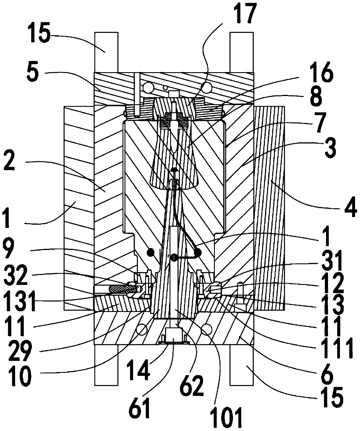
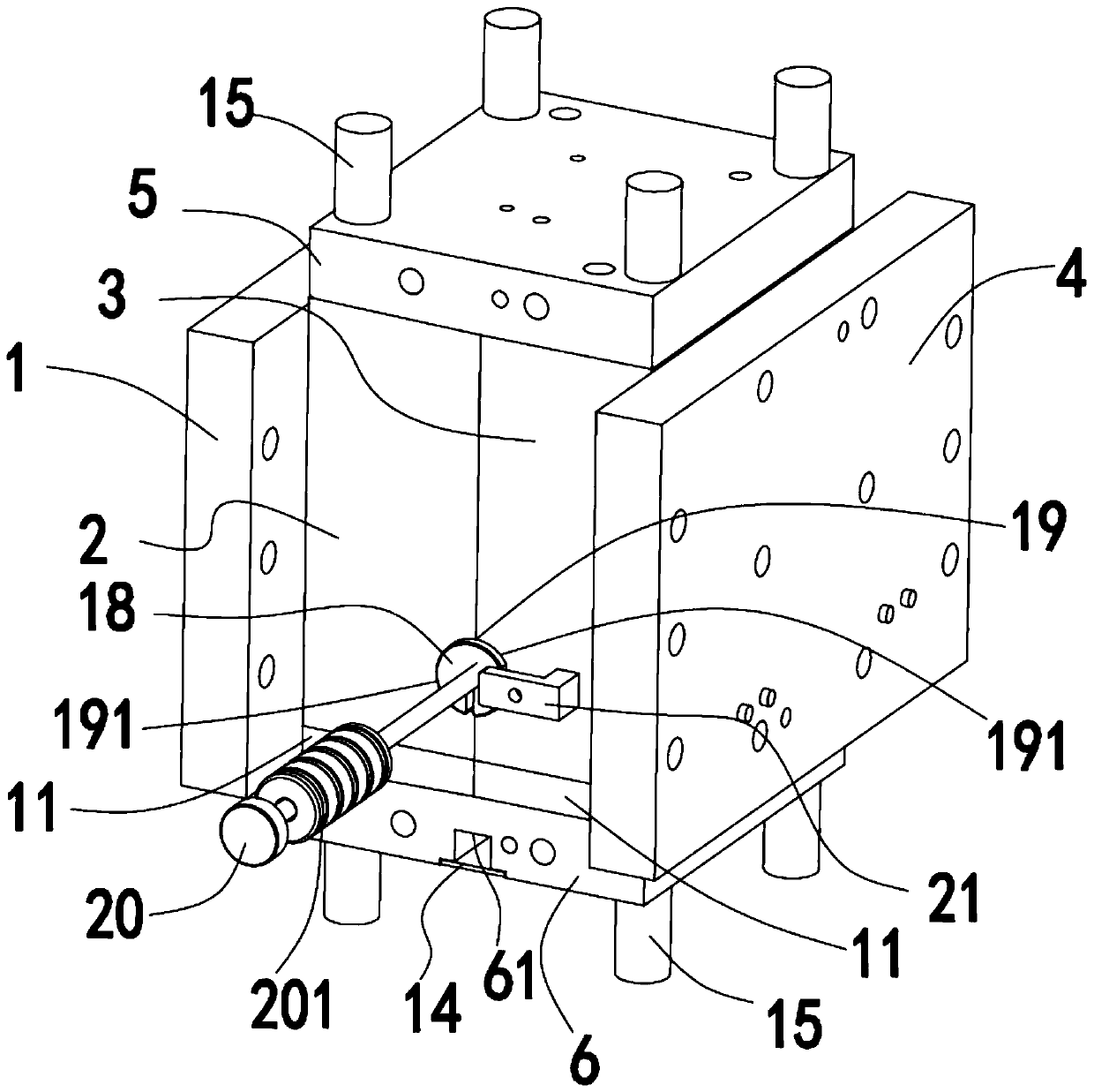
[0023] Such as Figure 1-Figure 5 As shown, the high-voltage probe precision injection molding mold applied to X-ray equipment described in this embodiment includes a fixed mold plate 1, a core block 2, a core block 3 and a fixed mold plate from front to back. 4. The movable mold fixed plate 1 is fixed on the front side of the movable mold core block 2, and the fixed mold fixed plate 4 is fixed on the rear side of the fixed mold core block 3; the upper side of the movable mold core block 2 and the fixed mold core block 3 are set Die fixed plate 5, the lower mold fixed plate 6 is arranged on the side of its lower part, and the upper side of the lower mold fixed plate 6 is fixed with a conical core-pulling body 10 for forming a tapered hole at the bottom of the product; The cavity 71 of the cavity 71 and the cavity 71 on the front side of the fixed mold core block 3 are combined to form a cavity 7 with a positioning structure in the lower opening and a through opening in the upp...


PUM


Abstract

The invention provides a high-voltage probe precision injection molding mold applied to the x-ray equipment. A movable mold fixing plate is fixed on a movable mold core block, a fixed mold fixing plate is fixed on the rear side surface of a fixed mold core block, an upper mold fixing plate is arranged on the upper side surfaces of the movable mold core block and the fixed mold core block, a lowerdie fixing plate is arranged on the lower side face of a lower die fixing plate, a conical core pulling body is fixed on the upper side face of the lower die fixing plate, the movable mold core blockand the fixed mold core block are spliced to form a mold cavity, a column type embedded part is arranged in an opening in the upper part of the mold cavity, the upper part of the column type embeddedpart is positioned on the lower side surface of the upper mold fixing plate, an annular embedded part is positioned at the lower part opening of the column type embedded part, the upper end part of the core pulling body is inserted into the insertion hole in the bottom end of the column type embedded part, the two side parts of the mold cavity are provided with a core pulling die head, the core pulling die head is arranged between the movable mold core block and the fixed mold core block, two flexible core pulling parts which are spirally arranged are arranged in the mold cavity, and the tailend of the flexible core pulling part is fixedly connected with the forming end part of the core pulling die head. The structure of the equipment has the advantages of improving rate of finished products and production efficiency.

Description

technical field [0001] The invention relates to the technical field of injection molding molds, in particular to a precision injection molding mold for high-voltage probes used in X-ray equipment. Background technique [0002] At present, the X-ray high-voltage probe is used in X-ray equipment. Because it has a double helix channel inside and is injection-molded by polymer materials, the embedded parts need to be pre-positioned inside the molding, so as to solve the problem in the prior art when the product is molded. Practical problems such as the need to form double helical channels, side holes, and the difficulty of achieving uniform injection molding after pre-positioning embedded parts during molding, low yield and production efficiency, must require some special structural designs to make the high-voltage probes used in X-ray equipment precise The injection molding mold structure is optimized to achieve a simple parting surface, uniform hot melt filling, high yield and...

Claims


Application Information

Patent Timeline
IPC IPC(8): B29C45/26B29C45/14B29C45/33B29L31/34
Inventor 欧吉飞吴阿福
Owner 宁波喆昊模具有限公司
Why Eureka
Try Eureka