
M-type bag forming clamping device

A bag holder and bag forming technology, applied in the field of packaging equipment, can solve the problems of low coordination, complex and bulky structure of the M-bag bag holder, and low packaging efficiency, so as to achieve compact equipment structure, reduce dust overflow and improve packaging. The effect of efficiency

Pending Publication Date: 2019-06-07
XIAN MAGNETIC FOREST ELECTROMATIC
View PDF0 Cites 10 Cited by
  • Summary
  • Abstract
  • Description
  • Claims
  • Application Information

AI Technical Summary

Problems solved by technology

[0004] The purpose of the present invention is to solve the disadvantages of the existing M-bag bag holder with complex and large structure, low matching degree and low packaging efficiency, and provide a M-bag forming bag holder, which is suitable for the process of using M-bag for material packaging process

Method used


Image

  • M-type bag forming clamping device
  • M-type bag forming clamping device
  • M-type bag forming clamping device

Examples


Embodiment Construction

[0039] Below in conjunction with accompanying drawing and specific embodiment content of the present invention is described in further detail:

[0040] For the sake of convenience only, in the following description, specific direction terms are used, which are referred to the corresponding drawings, and cannot be considered as limitations on the present invention. When the defined directions of the drawings change, these The directions indicated by the words should be interpreted as corresponding different directions.

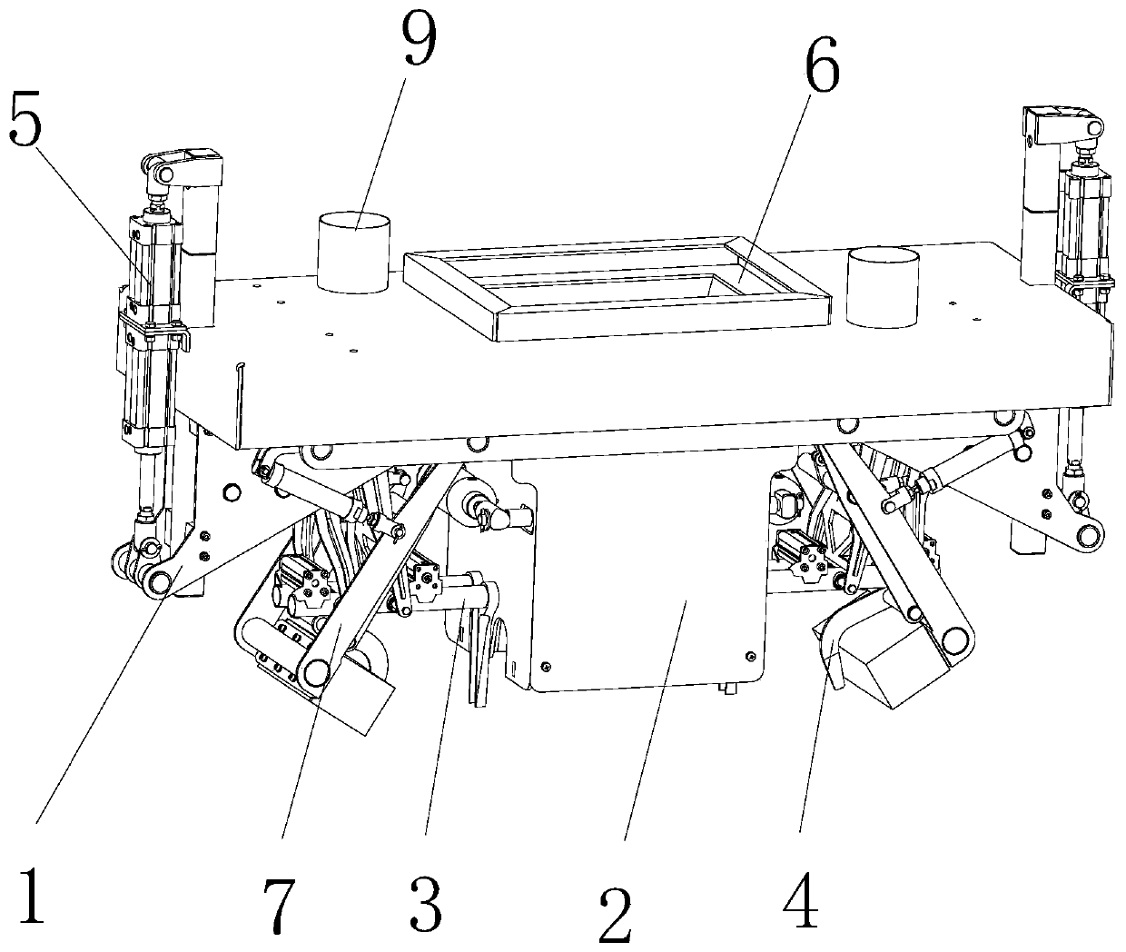
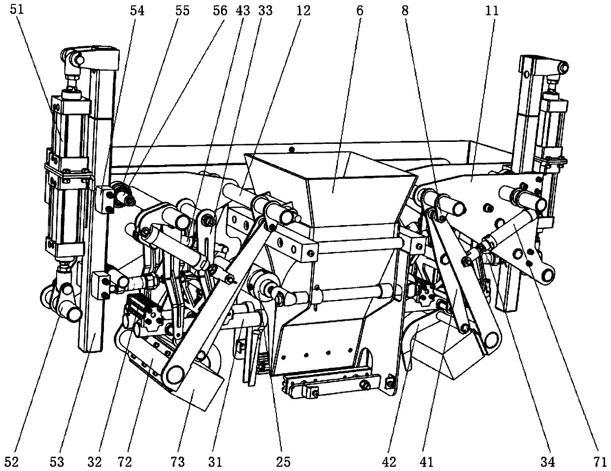
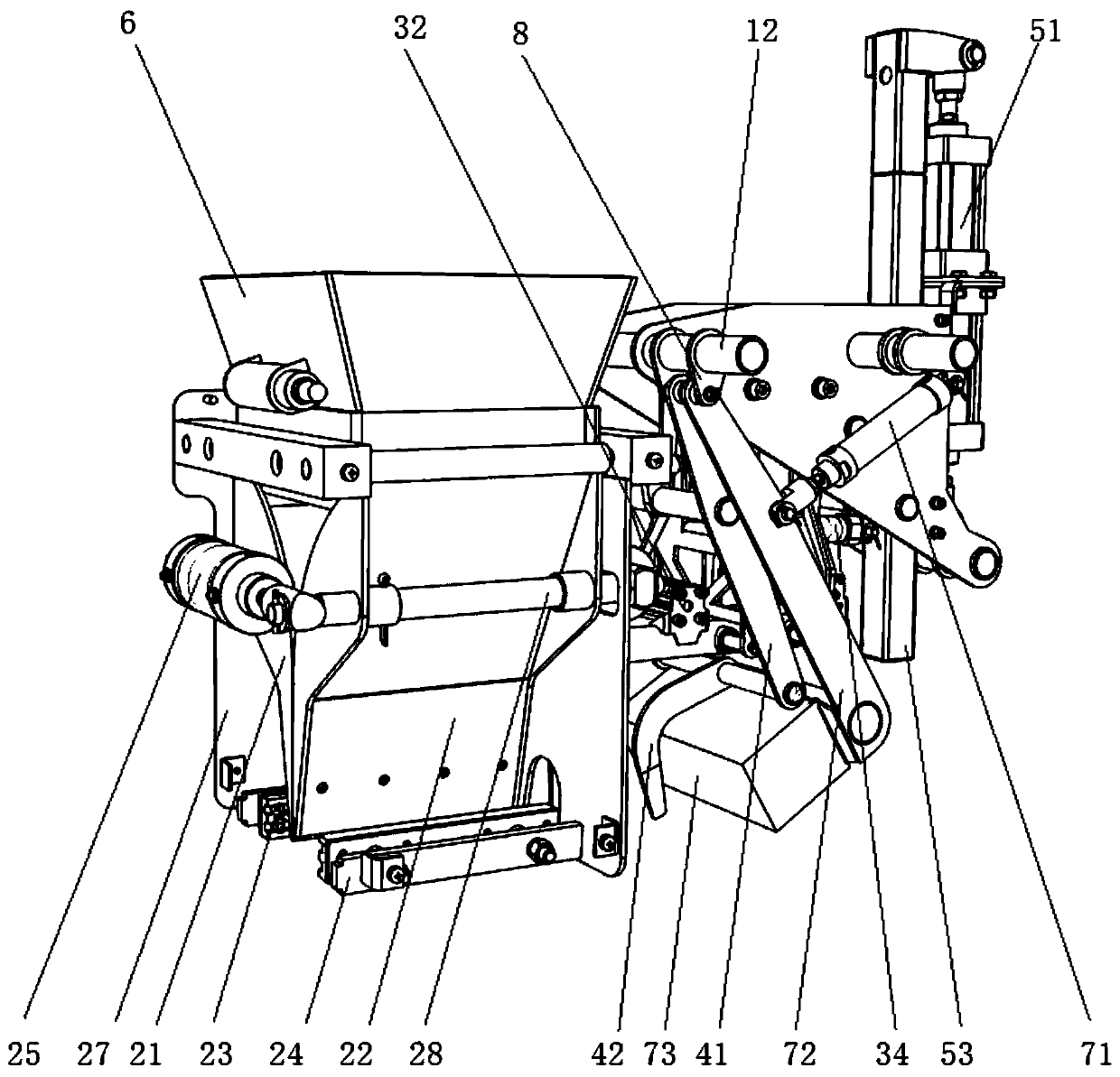
[0041] Such as Figure 1-Figure 9 As shown, the M-bag forming bag clamp includes a mounting frame 1, a bag clamping assembly 2, two sets of bag support bar assemblies 3, two sets of M forming assemblies 4, two sets of cover bag assemblies 7 and two sets of lifting assemblies 5.

[0042] Wherein, the mounting frame 1 includes two sets of mounting plates 11 and two beams 13; each set of mounting plates includes two mounting plates 11, and the two mounting plates...


PUM


Abstract

The invention provides an M-type bag forming clamping device. The M-type bag forming clamping device solves the problems of complex and large structure, low matching degree and low packaging efficiency of an existing M-type bag clamping device. The M-type bag forming clamping device comprises a mounting frame, a bag clamping assembly, two bag supporting rod assemblies, two M-type bag forming assemblies and two lifting assemblies, wherein the mounting frame is connected with the lifting assemblies; the lifting assemblies are fixedly arranged on a discharging device and used for driving the mounting frame to move up and down; the bag clamping assembly is arranged at a discharging opening of the discharging device; the two bag supporting rod assemblies are arranged on the mounting frame, corresponding to two sides of the discharging device, and used for performing bag supporting action on an M-type bag; each bag supporting rod assembly comprises two bag supporting rods, two bag supportingcylinders, two swing frames and a swing cylinder; the two M-type bag forming assemblies are arranged on the mounting frame, correspondingly arranged on two sides of the discharging device, and used for performing M-type forming recovery action on the M-type bag; each M-type bag forming assembly comprises a forming frame, a forming sheet and a forming cylinder; and the movement area of the formingsheet is in the middle of the bag supporting rod assemblies.

Description

technical field [0001] The invention belongs to packaging equipment, in particular to an M-bag forming bag holder. Background technique [0002] The bag gripper is one of the important components of the packaging equipment. With the requirements for high-efficiency, intelligent and automatic operation of the material packaging equipment, a variety of automatic bag grippers have also emerged. [0003] At present, there are many types of packaging bags used in the packaging of granular materials and powder materials. When using ordinary packaging bags, the bag holder clamps the packaging bag to complete blanking, thereby completing automatic blanking; On the side, the bag-holding rod extended into the bag mouth in advance exerts force, which will stretch the bag mouth of the packaging bag, and then send it to the bag pushing device to carry out the subsequent process of folding and sewing the packaging bag. However, this type of bag gripper is not suitable for the common M-ba...

Claims


Application Information

Patent Timeline
Patent Type & Authority Applications(China)
IPC IPC(8): B65B43/54B65B43/34B65B1/28
Inventor 马玉林李玉珊刘航运
Owner XIAN MAGNETIC FOREST ELECTROMATIC
Learn More