
Diversion tunnel body gate wellbore temporarily sealing and blocking method and device

A technology of diversion tunnels and gate wells, which is applied in water conservancy projects, hydroelectric power stations, hydroelectric power generation, etc., can solve the problems of high risk of gas explosion, harmful structures around the wellbore, time-consuming and labor-intensive problems, and achieve increased discharge volume and project cost Low cost and easy layout

Pending Publication Date: 2019-06-07
CHINA POWER CONSRTUCTION GRP GUIYANG SURVEY & DESIGN INST CO LTD
View PDF0 Cites 1 Cited by
  • Summary
  • Abstract
  • Description
  • Claims
  • Application Information

AI Technical Summary

Problems solved by technology

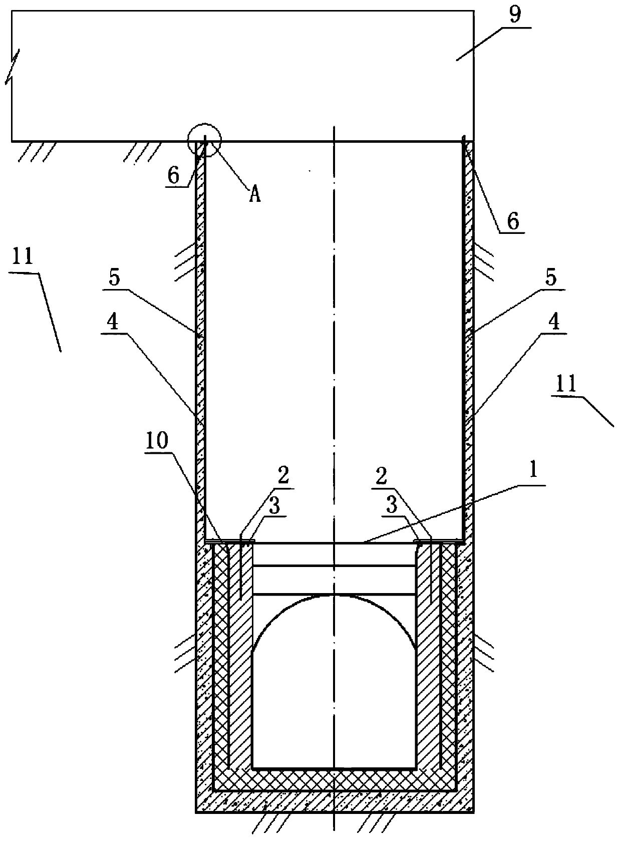
At present, the existing technology usually uses a length of concrete plug to seal the construction branch hole connecting the wellbore and the outside world. This method mainly has the following problems: First, there is a section of air between the wellbore section and the concrete section where the plugging body is set. , under high head pressure, the risk of gas explosion is greater
Secondly, before the diversion tunnel is lowered, the plugging concrete needs to be removed by blasting, which is harmful to the structure around the wellbore and is time-consuming and labor-intensive.

Method used


Image

  • Diversion tunnel body gate wellbore temporarily sealing and blocking method and device
  • Diversion tunnel body gate wellbore temporarily sealing and blocking method and device
  • Diversion tunnel body gate wellbore temporarily sealing and blocking method and device

Examples


Embodiment Construction

[0018] The following will clearly and completely describe the technical solutions in the embodiments of the present invention with reference to the accompanying drawings in the embodiments of the present invention. Obviously, the described embodiments are only some, not all, embodiments of the present invention. Based on the embodiments of the present invention, all other embodiments obtained by persons of ordinary skill in the art without making creative efforts belong to the protection scope of the present invention.

[0019] In the description of the present invention, it should be noted that, unless otherwise specified and limited, the terms "installed", "set with", "sleeved / connected", "connected", etc. should be understood in a broad sense, such as " Connection" can be a fixed connection, a detachable connection, or an integral connection; it can be a mechanical connection or an electrical connection; it can be a direct connection or an indirect connection through an inte...


PUM


Abstract

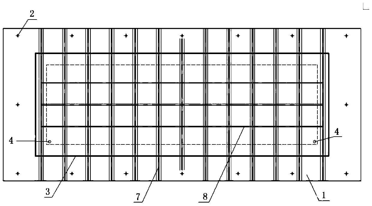
The invention discloses a diversion tunnel body gate wellbore temporarily sealing and blocking method and device, which comprises a sealing and blocking steel plate arranged on a diversion tunnel gatewell wellbore, the outer end of the sealing and blocking steel plate is connected with diversion tunnel gate well wellbore concrete in a diversion tunnel sealing and blocking gate locking platform byanchor bolts, and rubber sealing is arranged at the joint; an air exhaust steel pipe is arranged in the upward direction of the sealing and blocking steel plate and extends to a lock chamber sectionconstruction branch tunnel, and a check valve is arranged in the position where the top of the air exhaust pipe reaches the lock chamber section construction branch tunnel. According to thediversiontunnel body gate wellbore temporarily sealing and blocking method and device,by sealing and blocking the tunnel body gate well wellbore andinterceptingapressure diversion tunnel gate well wellbore air inlet passage, leakage of the diversion tunnel is increased;the sealing and blocking wellbore prevents the high water head water from flowing through the wellbore to other downstream caverns;under theaction of the diversion tunnel high water head, the sealing and blocking device of the diversion tunnel body gate wellbore temporarily sealing and blocking method and device can be automatically vented to prevent the air of the lock chamber section from generating a gas explosion under high pressure; and at the same time, the air can be depressurized through the check valve, and the pressure on the outside and the inside of the steel plate is identical after the water is passed.

Description

technical field [0001] The invention belongs to a device for temporarily blocking a channel of a diversion tunnel to block a gate shaft in a hydropower project, and in particular relates to a method and a device for temporarily blocking a diversion tunnel body gate shaft. Background technique [0002] Due to the constraints of terrain and construction road conditions in water conservancy and hydropower projects, the diversion tunnel plugging gate wells are often arranged in the tunnel chamber. Since the gate shaft of the diversion tunnel is connected with the outside atmosphere, the pressurized flow head formed by the self-flow of this type of tunnel is higher than the value calculated by the conventional empirical formula. In order to reduce the inlet channel of the pressurized tunnel, increase the discharge capacity of the diversion tunnel, and reduce the water pouring downstream from the shaft section of the gate shaft when the diversion tunnel has high head flow, it is n...

Claims


Application Information

Patent Timeline
Patent Type & Authority Applications(China)
IPC IPC(8): E02B9/06
CPCY02E10/20
Inventor 王向予崔进郭勇邱焕峰张成刘明
Owner CHINA POWER CONSRTUCTION GRP GUIYANG SURVEY & DESIGN INST CO LTD
Learn More