Pneumatic circulation air compression pump and air engine combined body

An air engine and air pressure pump technology, applied in the direction of rotating or swinging piston engine, machine/engine, rotating piston engine, etc. and other problems, to achieve the effect of low gas consumption and high efficiency

Inactive Publication Date: 2019-06-07
张谭伟
View PDF0 Cites 2 Cited by
  • Summary
  • Abstract
  • Description
  • Claims
  • Application Information

AI Technical Summary

Problems solved by technology

[0002] Compressed air engines are power machinery for transportation, industry, electric power, etc., and are widely used in mobile equipment such as air-powered vehicles and air power generation. However, the existing air compressors have low gas production, high air consumption of air engines, and cannot circulate compressed air. use

Method used


Image

  • Pneumatic circulation air compression pump and air engine combined body
  • Pneumatic circulation air compression pump and air engine combined body
  • Pneumatic circulation air compression pump and air engine combined body

Examples


Embodiment 1

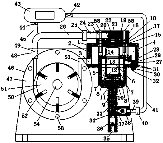
[0025] refer to Figure 1-Figure 4 , a combination 1 of a pneumatic circulating air compressor and an air engine, including a pneumatic circulating air compressor and a vane air engine 6;

[0026] The pneumatic circulating air pump includes a pneumatic circulating air pump housing 2, a pneumatic circulating air pump inlet 3, an intake gas storage chamber 4, a piston return chamber 5, a cylinder I 6, and a cylinder inlet to the piston return chamber. Air outlet 7, piston air return port 8, piston I9, gasket I10, sealing ring I11, sealing ring II12, sealing ring III13, cylinder head piston 14, sealing ring IV15, sealing ring V16, cylinder head 17, air inlet of cylinder head 18. Cylinder head air storage chamber 19, sealing ring Ⅵ20, sealing gasket Ⅱ21, cylinder exhaust cover 22, exhaust cover air outlet 23, joint Ⅰ24, check valve Ⅰ25, return air pipe 26, switch 27, air intake of switch cavity Port 28, switch air cavity outlet 29, switch lock nut 30, seal ring VII31, switch air ...

Embodiment 2

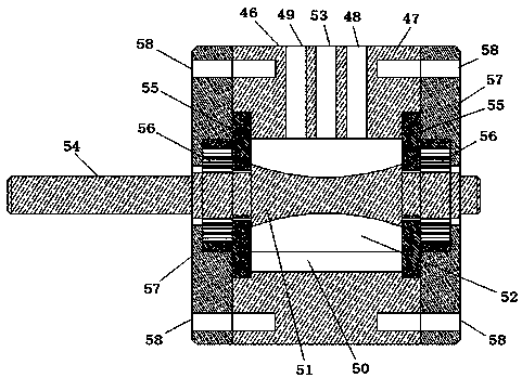
[0031] refer to Figure 4-Figure 5 , a combination 1 of a pneumatic circulating air compressor and an air engine, comprising a pneumatic circulating air compressor and a piston air engine;

[0032] The pneumatic circulating air pump includes a pneumatic circulating air pump housing 2, a pneumatic circulating air pump inlet 3, an intake gas storage chamber 4, a piston return chamber 5, and an air outlet 7 for the cylinder inlet piston return chamber , Piston air return port 8, gasket Ⅰ10, sealing ring Ⅰ11, sealing ring Ⅱ12, sealing ring Ⅲ13, cylinder head piston 14, sealing ring Ⅳ15, sealing ring Ⅴ16, cylinder head 17, cylinder head air inlet 18, cylinder head gas storage Cavity 19, sealing ring Ⅵ20, gasket Ⅱ21, cylinder exhaust cover 22, exhaust cover outlet 23, joint Ⅰ24, check valve Ⅰ25, air return pipe 26, switch 27, switch air cavity inlet 28, switch air cavity Air outlet 29, switch lock nut 30, sealing ring VII 31, switch air rod 32, air compressor air storage tank 43, a...

Embodiment 3

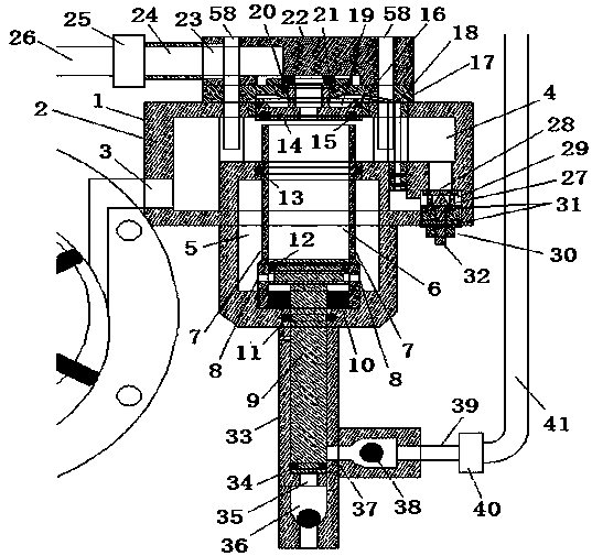
[0035] refer to Figure 4 and Image 6 , a combination 1 of a pneumatic circulating air compressor and an air engine, comprising a pneumatic circulating air compressor and a piston air engine;

[0036] The pneumatic circulating air pump includes a pneumatic circulating air pump housing 2, a pneumatic circulating air pump inlet 3, an intake gas storage chamber 4, a cylinder head piston 14, a sealing ring IV15, a sealing ring V16, and a cylinder head 17 , cylinder head air inlet 18, cylinder head air storage chamber 19, sealing ring Ⅵ20, sealing gasket Ⅱ21, cylinder exhaust cover 22, exhaust cover air outlet 23, joint Ⅰ24, check valve Ⅰ25, air return pipe 26, switch 27 , switch air cavity inlet 28, switch air cavity outlet 29, switch lock nut 30, sealing ring VII 31, switch air rod 32, air compressor air storage tank 43, air compressor exhaust valve 44, air compressor Exhaust pipe 45; the piston air engine includes cylinder II 63, piston II 64, piston connecting rod pin 59, co...


PUM


Abstract

A pneumatic circulation air compression pump and air engine combined body comprises a pneumatic circulation air compression pump and a blade type air engine. The pneumatic circulation air compressionpump comprises a pneumatic circulation air compression pump shell, a pneumatic circulation air compression pump air inlet, an air inlet air storage cavity, a piston air return cavity, an air cylinderI, an air outlet of an air cylinder inlet piston air return cavity, a piston air return port, a piston I, a seal pad I, a seal ring I, a seal ring II, a seal ring III, an air cylinder cover piston, aseal ring IV, a seal ring V, an air cylinder cover, an air cylinder cover air inlet, an air cylinder cover air storage cavity, a seal ring VI, a seal pad II, an air cylinder exhaust cover, an exhaustcover air outlet, a connector I, a check valve I, an air return pipe, a switch, a switch locking nut, a seal ring VII, a switch gas rod, a compressed air cylinder and a seal ring VIII. The pneumatic circulation air compression pump and air engine combined body can cyclically utilize compressed air and has the characteristics of being high in efficiency, low in air consumption and the like.

Description

technical field [0001] The invention relates to a combination of a pneumatic circulating air compressor and an air motor. Background technique [0002] Compressed air engines are power machinery for transportation, industry, electric power, etc., and are widely used in mobile equipment such as air-powered vehicles and air power generation. However, the existing air compressors have low gas production, high air consumption of air engines, and cannot circulate compressed air. use. Contents of the invention [0003] The technical problem to be solved by the present invention is to provide a combination of a pneumatic circulating air compressor and an air engine capable of recycling compressed air. [0004] The technical solution adopted by the present invention to solve its technical problems is: [0005] Technical solution 1: a combination of a pneumatic circulating air compressor and an air engine, including a pneumatic circulating air compressor and a vane air engine; ...

Claims


Application Information

Patent Timeline
Patent Type & Authority Applications(China)
IPC IPC(8): F01C1/344F01B29/10F04B35/02
Inventor 张谭伟
Owner 张谭伟
Why Eureka
Try Eureka