A butterfly valve with an anti-seize structure and its application method

An anti-seize, butterfly valve technology, applied in the valve shell structure, devices to prevent accidental or unauthorized action, lift valves, etc. problem, to achieve the effect of ease of use and labor-saving control operation

Active Publication Date: 2019-12-06
阿奥艾斯能源科技成都有限公司
View PDF7 Cites 1 Cited by
  • Summary
  • Abstract
  • Description
  • Claims
  • Application Information

AI Technical Summary

Problems solved by technology

[0003] The existing butterfly valve equipment has certain disadvantages in the use process. The traditional butterfly valve adopts a single-axis transmission structure. When the user closes or opens the butterfly valve, the force exerted by the user directly acts on the handle of the butterfly valve, and the butterfly valve is driven by the handle. Complete the closing or opening operation, which makes the opening or closing operation of the butterfly valve more laborious. The traditional butterfly valve does not have a combined fixed structure, so that a single butterfly valve can be used for docking and fixing operations on pipes with a uniform caliber, which reduces the scope of use of single butterfly valves. It only has a single sealing structure. After the butterfly valve is used for a long time, the internal sealing structure of the butterfly valve is prone to phenomena, which will have a certain impact on the opening of the butterfly valve and bring certain adverse effects to the user.

Method used


Image

  • A butterfly valve with an anti-seize structure and its application method
  • A butterfly valve with an anti-seize structure and its application method
  • A butterfly valve with an anti-seize structure and its application method

Examples


Embodiment Construction

[0036] The technical solutions in the embodiments of the present invention will be clearly and completely described below in conjunction with the embodiments of the present invention. Apparently, the described embodiments are only some of the embodiments of the present invention, not all of them. Based on the embodiments of the present invention, all other embodiments obtained by persons of ordinary skill in the art without creative efforts fall within the protection scope of the present invention.

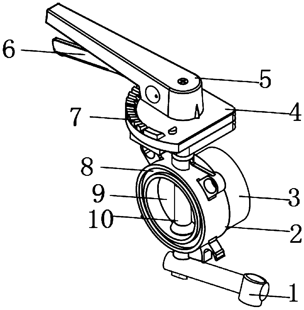
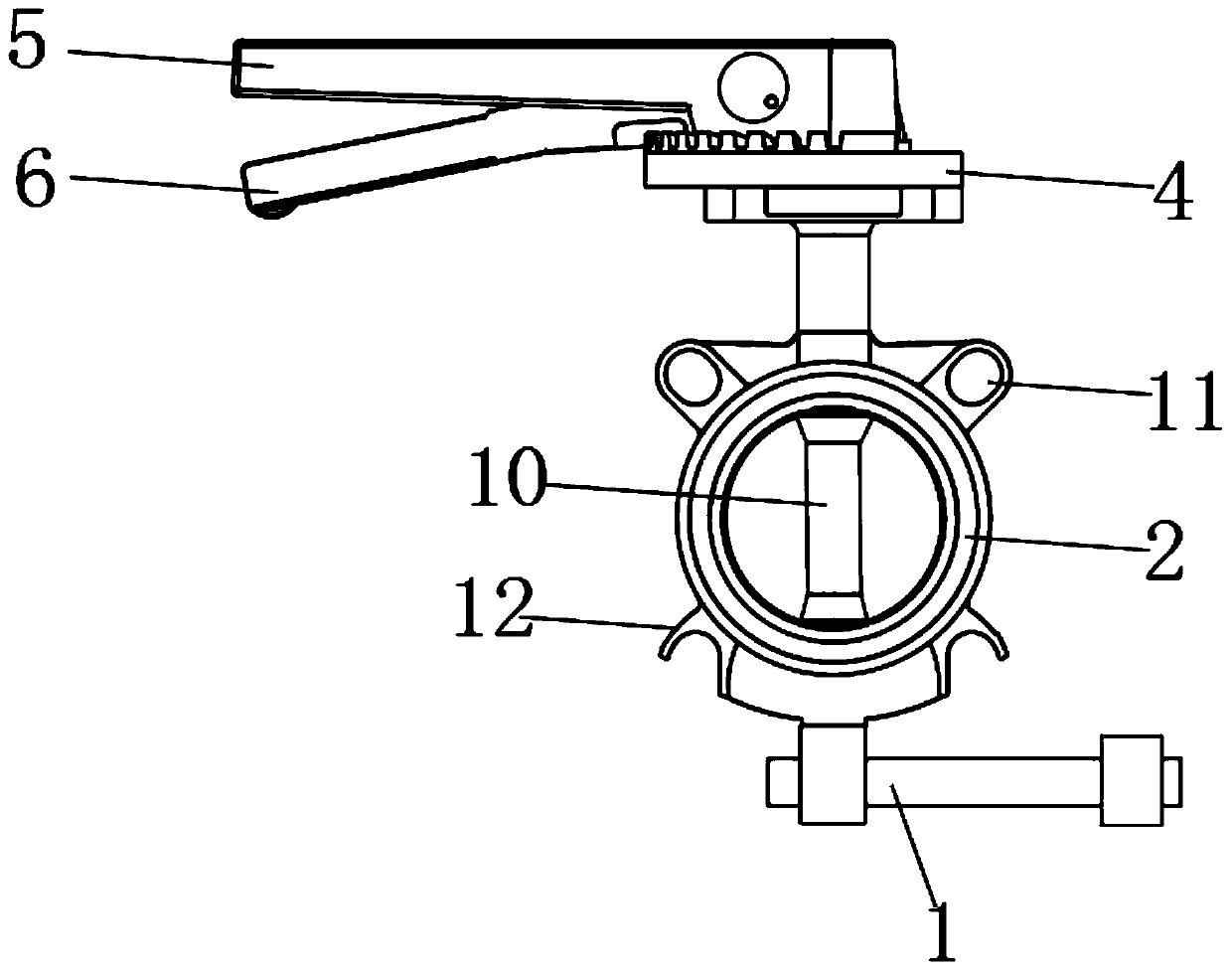
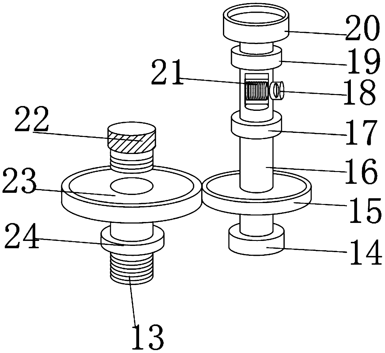
[0037] like Figure 1-8 As shown, a butterfly valve with an anti-seize structure includes a docking valve body 2, an interlocking rotating rod 16, a locking pressure rod 6, a combination card seat 3, a sealing card plate 42, an auxiliary rotating rod 1, and a baffle collar 9 and the sliding inner rod 30, the upper part of the combined deck 3 is fixedly equipped with a corner clip 4, and the interlocking rotating rod 16 is movably socketed on the inner side of the corner clip 4, an...


PUM


Abstract

The invention discloses a butterfly valve with an anti-jam structure and an application method of the butterfly valve. The butterfly valve comprises a butting valve body, an interlocking rotating rod,a locking pressure rod, a combined clamping seat, an airtight clamping plate, an auxiliary rotating rod, a baffle lantern ring and a sliding inner rod, wherein a corner clamping plate is fixedly mounted at the upper part of the combined clamping seat; the interlocking rotating rod is movably connected to the inner side of the corner clamping plate in a sleeving manner, and is in butting fixationto the corner clamping plate through an airtight top cover; a first rotating disk is fixedly connected to the outer surface of the interlocking rotating rod in a sleeving manner; a spring top buckle is movably mounted at the upper part adjacent to a first rotating disk, of the outer surface of the interlocking rotating rod; and the interlocking rotating rod is in butting fixation to the spring topbuckle through a spring pin. According to the butterfly valve with the anti-jam structure and the application method of the butterfly valve disclosed by the invention, the butterfly valve has a dualregulating structure, so that the phenomenon of jam is effectively avoided, a single butterfly valve can be applied to pipe fittings of different calibers, the application range is enlarged, and the operation of regulating is more labor-saving.

Description

technical field [0001] The invention belongs to the technical field of valve equipment, and in particular relates to a butterfly valve with an anti-seize structure, in particular to a butterfly valve with an anti-seize structure and a use method thereof. Background technique [0002] Butterfly valve, also known as flap valve, is a regulating valve with simple structure, which can be used for switch control of low-pressure pipeline medium. A kind of valve, the valve can be used to control the flow of various types of fluids such as air, water, steam, various corrosive media, mud, oil, liquid metal and radioactive media. It mainly plays the role of cutting and throttling on the pipeline. The opening and closing part of the butterfly valve is a disc-shaped butterfly plate, which rotates around its own axis in the valve body, so as to achieve the purpose of opening and closing or adjustment; [0003] The existing butterfly valve equipment has certain disadvantages in the use p...

Claims


Application Information

Patent Timeline
Patent Type & Authority Patents(China)
IPC IPC(8): F16K1/22F16K3/02F16K27/02F16K27/04F16K31/44F16K31/60F16K35/02F16K35/10F16L37/127
Inventor 许天杰
Owner 阿奥艾斯能源科技成都有限公司
Why Eureka
Try Eureka